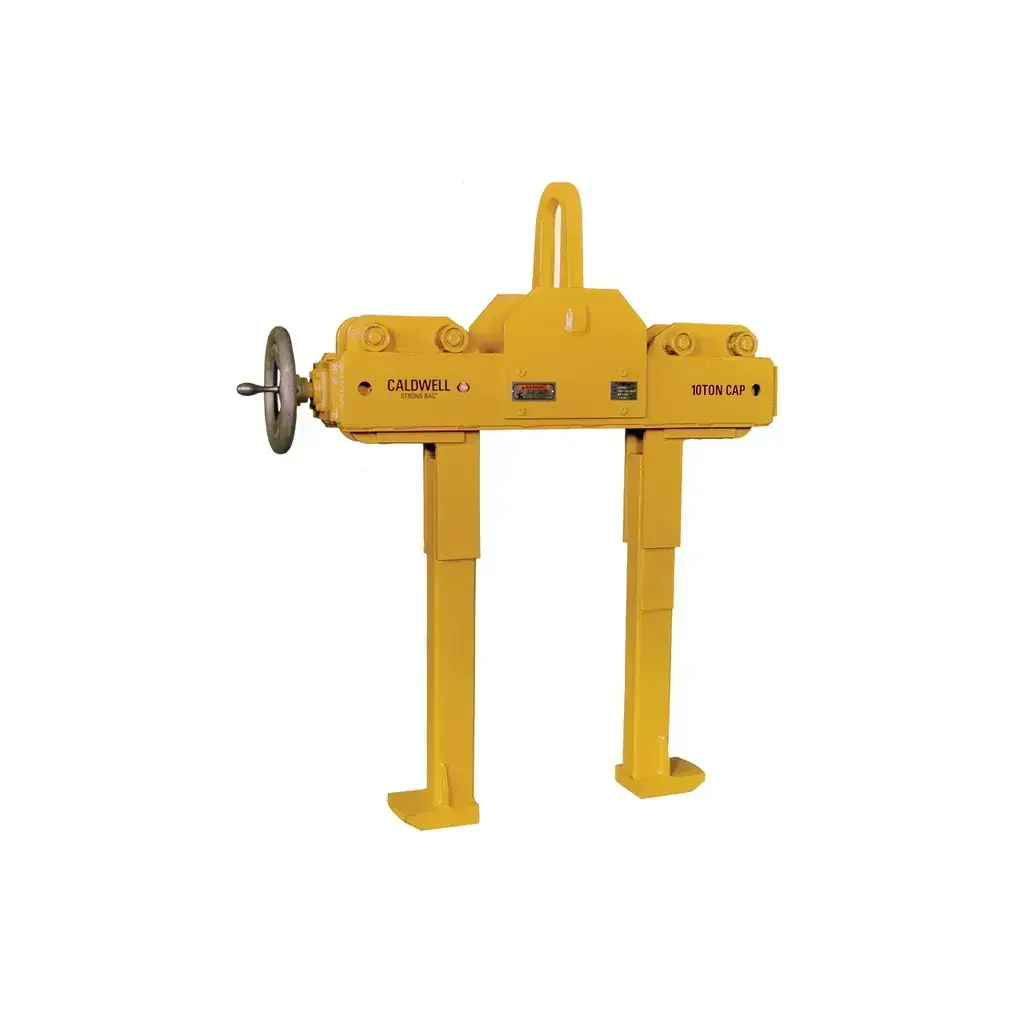
Caldwell Model GC Girder Clamp — 15–25 Ton
Caldwell Model GC Girder Clamps — Reliable Vertical Lifting for Wide Flange Beams & Plate Girders
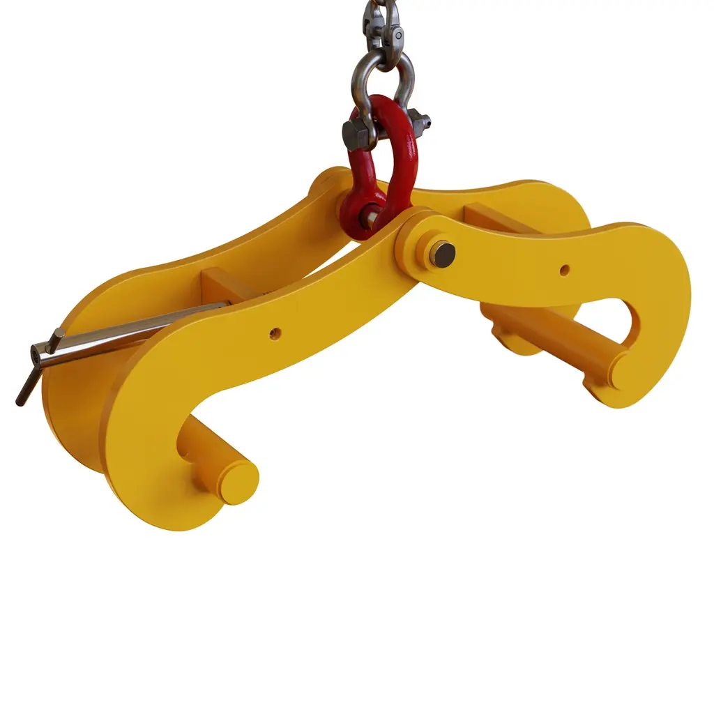
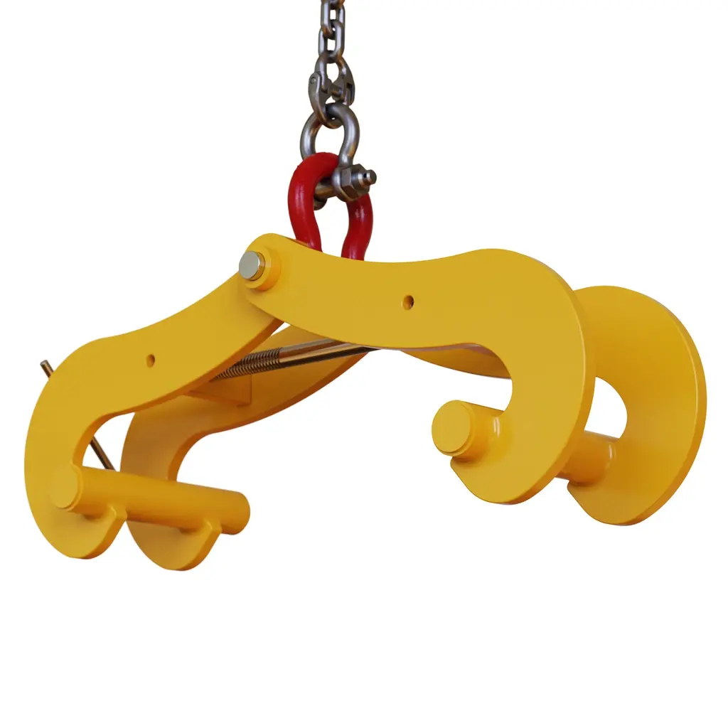
The Caldwell Model GC Girder Clamp is a heavy-duty construction lifting device engineered specifically for handling wide flange beam sections and plate girders in vertical lifting applications. Available in three rated capacities — 15, 20, and 25 tons — these clamps are stocked and ready to ship, making them a dependable choice for steel erection, bridge construction, and structural beam placement. The screw-spindle clamping mechanism engages a broad range of flange widths (6 in. to 24 in.) and accommodates flange thicknesses up to 3 in., giving contractors versatility across a wide variety of structural steel profiles. Compliant with ASME standards, the GC series meets the safety and performance requirements demanded on regulated job sites.
Unlike lever-operated or chain-style beam clamps, the Model GC's left-hand and right-hand threaded screw spindle design enables rapid simultaneous clamping and unclamping with minimal effort, significantly reducing rigging time during high-volume lifts. The straightforward mechanical design minimizes the number of moving parts, resulting in lower maintenance demands and a longer service life even under the repeated heavy-use conditions typical of structural steel work. For additional stability on long-span members, two GC clamps can be used in tandem with a spreader beam.
Key Features & Benefits
Screw-Spindle Positive Grip
The screw-spindle design applies consistent, mechanically secured clamping force directly to the beam flange, eliminating the risk of slippage that can occur with spring-loaded or gravity-dependent clamps. For contractors lifting heavy structural members overhead, this positive grip is a critical safety advantage. The clamp stays locked until deliberately released, providing a secure hold throughout the entire lift cycle.
Left- and Right-Hand Thread for Rapid Actuation
The opposing thread configuration on the screw spindle means both clamping jaws close simultaneously with a single turning motion, cutting rigging and de-rigging time in half compared to single-threaded designs. On busy steel erection sites where beam placement cycles are frequent, this speed advantage directly reduces crane time and labor costs. The same mechanism allows equally fast release once the beam is set in position.
Wide Jaw Adjustment Range
With a flange width accommodation range of 6 in. to 24 in. and a maximum flange thickness of 3 in., the Model GC adapts to a broad spectrum of standard wide flange (W-shape) sections and built-up plate girders without requiring tool changes or accessory kits. This versatility makes a single clamp useful across multiple beam sizes on the same project, reducing the total number of rigging devices a crew needs to keep on site.
Minimal Maintenance Design
The Model GC's uncomplicated mechanical construction — featuring a screw spindle, rigid frame, and curved jaw profiles — minimizes components that can wear, corrode, or require periodic calibration. For contractors working in outdoor or harsh environments, fewer maintenance touchpoints mean less downtime and lower ownership costs over the equipment's service life. Inspection before each lift is straightforward, supporting compliance with pre-use equipment check requirements.
ASME Standard Compliance
All Model GC Girder Clamps comply with ASME standards for lifting devices, ensuring they meet the safety, load rating, and design criteria required on regulated construction and industrial job sites. Compliance documentation supports contractor safety programs and may be required for project submittals or third-party inspections. Using ASME-compliant rigging hardware is standard practice for liability management on commercial and infrastructure projects.
Paired Use with Spreader Beam
The Model GC is designed to work in pairs in conjunction with a spreader beam, distributing the load across two pick points for improved stability when handling long-span beams or girders prone to lateral instability during lifting. This configuration is particularly valuable on bridge deck and heavy structural framing projects where beam lengths exceed practical single-point lift limits. Using matched capacity clamps ensures balanced load sharing across the rigging system.
Common Applications
Structural Steel Erection
The Model GC is purpose-built for lifting and positioning structural wide flange beams during steel frame construction, providing a secure grip on standard W-shape sections across the full range of commercially available flange widths.
Bridge Construction & Maintenance
Plate girders used in bridge superstructures often exceed standard beam dimensions; the GC's 24 in. maximum flange width and up to 25-ton capacity accommodate the heavy plate girder profiles common in bridge fabrication and erection work.
Industrial & Heavy Manufacturing Facilities
During the construction of industrial facilities such as warehouses, manufacturing plants, and power generation infrastructure, the GC clamps handle the large-capacity crane runway beams and heavy transfer girders that define these structures.
Precast & Fabrication Yard Beam Handling
Steel fabrication shops and precast yards use girder clamps to move completed beam assemblies from fabrication stations to staging areas or transport vehicles, where the speed of the screw-spindle mechanism improves shop floor throughput.
Infrastructure & Civil Construction
Retaining wall soldiers, sheet pile waler systems, and other civil infrastructure components using wide flange sections can be positioned precisely using the Model GC, which adjusts to the full range of section geometries encountered in civil work.
Crane & Rigging Operations
Rigging contractors requiring a reliable, ASME-compliant beam clamp for general-purpose overhead lifting of structural steel sections will find the Model GC's capacity range and jaw versatility suitable for a wide variety of project types and crane configurations.
Compatible Materials
- Wide flange (W-shape) structural steel beams
- Plate girders (built-up steel sections)
- Standard structural steel sections with flange widths from 6 in. to 24 in.
- Steel sections with flange thickness up to 3 in.
- Structural members requiring vertical-only lift orientation
Available Models
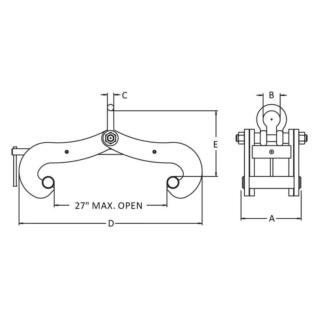
| Model Number | Rated Capacity (tons) | Flange Width Min–Max (in.) | Max Flange Thickness (in.) | Dim A — Shackle Open (in.) | Dim B — Shackle Thick (in.) | Dim C — Product Depth (in.) | Dim D — Max/Min W (in.) | Dim E — Max/Min HR (in.) | Weight (lbs.) | Best For |
|---|---|---|---|---|---|---|---|---|---|---|
| GC-15 | 15 | 6–24 | 3 | 3.9 | 1.6 | 14.81 | 23–44 | 15.7–23.4 | 235 | Light-to-medium structural steel erection; standard W-shape beams up to 15-ton vertical lifts |
| GC-20 | 20 | 6–24 | 3 | 5.0 | 2.1 | 14.81 | 23–44 | 18.3–25.9 | 291 | Medium-to-heavy structural beams and plate girders requiring 20-ton vertical lift capacity |
| GC-25 | 25 | 6–24 | 3 | 5.0 | 2.1 | 14.81 | 23–44 | 18.3–25.9 | 342 | Heavy plate girders, bridge beams, and large structural members requiring maximum 25-ton vertical capacity |
Product Documents
Application Instructions
Pre-Use Inspection
- Inspect the clamp frame, jaws, and screw spindle for cracks, deformation, wear, or corrosion before each use.
- Verify the rated capacity marked on the clamp meets or exceeds the load to be lifted.
- Confirm the shackle and all fasteners are properly secured and show no signs of damage.
- Check that the screw spindle threads are clean and move freely throughout their travel range.
Clamping & Rigging
- Open the jaws of the Model GC by rotating the screw spindle until the jaw opening exceeds the flange width of the beam to be lifted.
- Position the clamp over the beam flange, centering the jaws symmetrically on the flange.
- Rotate the screw spindle in the closing direction — the opposing left- and right-hand threads will simultaneously draw both jaws onto the flange until firm contact is achieved.
- Connect the crane hook or rigging hardware to the clamp's shackle. Ensure the shackle pin is fully seated and moused (secured).
- For long or heavy girders, rig a second GC clamp at the opposite end and use a spreader beam to equalize the load between both pick points.
Lifting & Placement
- Perform a trial lift of a few inches and hold to verify the clamp is seated correctly and the load is balanced before proceeding with the full lift.
- Use only vertical lifting — lateral, angular, or horizontal pulls are strictly prohibited and will compromise clamp integrity and load security.
- Lower the beam to its final position carefully. Do not shock-load the clamp.
- Once the beam is stable and bearing its own weight, rotate the screw spindle to open the jaws and remove the clamp.
Technical Specifications
| Specification | GC-15 | GC-20 | GC-25 |
|---|---|---|---|
| Rated Capacity (tons) | 15 | 20 | 25 |
| Flange Width Min. (in.) | 6 | 6 | 6 |
| Flange Width Max. (in.) | 24 | 24 | 24 |
| Max Flange Thickness (in.) | 3 | 3 | 3 |
| Dim A — Shackle Open (in.) | 3.9 | 5.0 | 5.0 |
| Dim B — Shackle Thick (in.) | 1.6 | 2.1 | 2.1 |
| Dim C — Product Depth (in.) | 14.81 | 14.81 | 14.81 |
| Dim D — Max W Closed (in.) | 44 | 44 | 44 |
| Dim D — Max W Open (in.) | 23 | 23 | 23 |
| Dim E — Max HR Closed (in.) | 23.4 | 25.9 | 25.9 |
| Dim E — Min HR Open (in.) | 15.7 | 18.3 | 18.3 |
| Max Open Width (in.) | 27 | 27 | 27 |
| Weight (lbs.) | 235 | 291 | 342 |
| Lift Orientation | Vertical only | Vertical only | Vertical only |
| Standards Compliance | ASME | ASME | ASME |
| Clamping Mechanism | Screw-spindle (LH + RH thread) | Screw-spindle (LH + RH thread) | Screw-spindle (LH + RH thread) |
| Compatible Use Configuration | Single or paired with spreader beam | Single or paired with spreader beam | Single or paired with spreader beam |
Safety Data Summary
Hazard Information
- For vertical lifting only — angular, side, or horizontal loading will overstress the clamp and may cause load drop
- Never exceed the rated capacity marked on the clamp
- Do not use damaged, cracked, or deformed clamps — remove from service immediately
- Suspended loads present a struck-by hazard — keep personnel clear of the lift zone at all times
Personal Protective Equipment
- Hard hat required in all areas where overhead lifting is occurring
- Steel-toed boots required when handling and rigging clamps
- High-visibility vest recommended in active crane lift zones
- Gloves recommended when handling clamp hardware
Safe Handling
- Inspect clamp before each use — check frame, jaws, spindle, and shackle
- Confirm load weight before selecting clamp capacity
- Ensure the screw spindle is fully tightened against the flange before initiating the lift
- Perform a test lift at low height and hold before proceeding to full elevation
- Store clamps in a dry location when not in use; protect threads from contamination and corrosion
- Follow all applicable OSHA rigging and lifting regulations and site-specific lift plans
Frequently Asked Questions
Q: Can the Model GC be used for horizontal or angled lifts?
A: No. The Model GC is rated for vertical lifting only. Using this clamp in any non-vertical orientation — including horizontal pulling or angled lifts — is strictly prohibited and will void the load rating. Always rig the clamp so the load hangs vertically below the shackle.
Q: What is the minimum flange width the GC will accept?
A: All three Model GC variants (15, 20, and 25 ton) accommodate a minimum flange width of 6 in. and a maximum of 24 in. The jaw opening adjusts continuously across this range to suit standard wide flange sections and built-up plate girders.
Q: Can two Model GC clamps be used together on the same beam?
A: Yes. The Model GC is specifically designed to be used in pairs in conjunction with a spreader beam. This tandem configuration distributes the load across two pick points, improving lateral stability for long-span structural members. Ensure both clamps are the same rated capacity and that the spreader beam is rated for the total load.
Q: Are these clamps available from stock or are they special order?
A: All three capacity variants — 15, 20, and 25 ton — are stocked by Caldwell and available for immediate shipment. Contact Diamond Tool Store for current availability and lead times.
Q: What standards do the Model GC clamps comply with?
A: The Model GC Girder Clamps comply with ASME standards for lifting devices. This makes them suitable for use on regulated construction sites and in industrial facilities where equipment compliance documentation may be required for safety submittals or inspections.
Q: How do I select the right capacity — 15, 20, or 25 ton?
A: Select the clamp capacity that meets or exceeds the actual weight of the beam or girder being lifted. Always apply an appropriate safety margin consistent with your site's rigging safety program and applicable regulations. When using two clamps in tandem with a spreader beam, each clamp must be rated for at least half of the total load weight, plus any rigging hardware weight.
Product Information
Product Information
Shipping & Returns
Shipping & Returns




Caldwell Model GC Girder Clamp — 15–25 Ton
Caldwell Model GC Girder Clamp — 15–25 Ton
Caldwell Model GC Girder Clamps — Reliable Vertical Lifting for Wide Flange Beams & Plate Girders
The Caldwell Model GC Girder Clamp is a heavy-duty construction lifting device engineered specifically for handling wide flange beam sections and plate girders in vertical lifting applications. Available in three rated capacities — 15, 20, and 25 tons — these clamps are stocked and ready to ship, making them a dependable choice for steel erection, bridge construction, and structural beam placement. The screw-spindle clamping mechanism engages a broad range of flange widths (6 in. to 24 in.) and accommodates flange thicknesses up to 3 in., giving contractors versatility across a wide variety of structural steel profiles. Compliant with ASME standards, the GC series meets the safety and performance requirements demanded on regulated job sites.
Unlike lever-operated or chain-style beam clamps, the Model GC's left-hand and right-hand threaded screw spindle design enables rapid simultaneous clamping and unclamping with minimal effort, significantly reducing rigging time during high-volume lifts. The straightforward mechanical design minimizes the number of moving parts, resulting in lower maintenance demands and a longer service life even under the repeated heavy-use conditions typical of structural steel work. For additional stability on long-span members, two GC clamps can be used in tandem with a spreader beam.
Key Features & Benefits
Screw-Spindle Positive Grip
The screw-spindle design applies consistent, mechanically secured clamping force directly to the beam flange, eliminating the risk of slippage that can occur with spring-loaded or gravity-dependent clamps. For contractors lifting heavy structural members overhead, this positive grip is a critical safety advantage. The clamp stays locked until deliberately released, providing a secure hold throughout the entire lift cycle.
Left- and Right-Hand Thread for Rapid Actuation
The opposing thread configuration on the screw spindle means both clamping jaws close simultaneously with a single turning motion, cutting rigging and de-rigging time in half compared to single-threaded designs. On busy steel erection sites where beam placement cycles are frequent, this speed advantage directly reduces crane time and labor costs. The same mechanism allows equally fast release once the beam is set in position.
Wide Jaw Adjustment Range
With a flange width accommodation range of 6 in. to 24 in. and a maximum flange thickness of 3 in., the Model GC adapts to a broad spectrum of standard wide flange (W-shape) sections and built-up plate girders without requiring tool changes or accessory kits. This versatility makes a single clamp useful across multiple beam sizes on the same project, reducing the total number of rigging devices a crew needs to keep on site.
Minimal Maintenance Design
The Model GC's uncomplicated mechanical construction — featuring a screw spindle, rigid frame, and curved jaw profiles — minimizes components that can wear, corrode, or require periodic calibration. For contractors working in outdoor or harsh environments, fewer maintenance touchpoints mean less downtime and lower ownership costs over the equipment's service life. Inspection before each lift is straightforward, supporting compliance with pre-use equipment check requirements.
ASME Standard Compliance
All Model GC Girder Clamps comply with ASME standards for lifting devices, ensuring they meet the safety, load rating, and design criteria required on regulated construction and industrial job sites. Compliance documentation supports contractor safety programs and may be required for project submittals or third-party inspections. Using ASME-compliant rigging hardware is standard practice for liability management on commercial and infrastructure projects.
Paired Use with Spreader Beam
The Model GC is designed to work in pairs in conjunction with a spreader beam, distributing the load across two pick points for improved stability when handling long-span beams or girders prone to lateral instability during lifting. This configuration is particularly valuable on bridge deck and heavy structural framing projects where beam lengths exceed practical single-point lift limits. Using matched capacity clamps ensures balanced load sharing across the rigging system.
Common Applications
Structural Steel Erection
The Model GC is purpose-built for lifting and positioning structural wide flange beams during steel frame construction, providing a secure grip on standard W-shape sections across the full range of commercially available flange widths.
Bridge Construction & Maintenance
Plate girders used in bridge superstructures often exceed standard beam dimensions; the GC's 24 in. maximum flange width and up to 25-ton capacity accommodate the heavy plate girder profiles common in bridge fabrication and erection work.
Industrial & Heavy Manufacturing Facilities
During the construction of industrial facilities such as warehouses, manufacturing plants, and power generation infrastructure, the GC clamps handle the large-capacity crane runway beams and heavy transfer girders that define these structures.
Precast & Fabrication Yard Beam Handling
Steel fabrication shops and precast yards use girder clamps to move completed beam assemblies from fabrication stations to staging areas or transport vehicles, where the speed of the screw-spindle mechanism improves shop floor throughput.
Infrastructure & Civil Construction
Retaining wall soldiers, sheet pile waler systems, and other civil infrastructure components using wide flange sections can be positioned precisely using the Model GC, which adjusts to the full range of section geometries encountered in civil work.
Crane & Rigging Operations
Rigging contractors requiring a reliable, ASME-compliant beam clamp for general-purpose overhead lifting of structural steel sections will find the Model GC's capacity range and jaw versatility suitable for a wide variety of project types and crane configurations.
Compatible Materials
- Wide flange (W-shape) structural steel beams
- Plate girders (built-up steel sections)
- Standard structural steel sections with flange widths from 6 in. to 24 in.
- Steel sections with flange thickness up to 3 in.
- Structural members requiring vertical-only lift orientation
Available Models
| Model Number | Rated Capacity (tons) | Flange Width Min–Max (in.) | Max Flange Thickness (in.) | Dim A — Shackle Open (in.) | Dim B — Shackle Thick (in.) | Dim C — Product Depth (in.) | Dim D — Max/Min W (in.) | Dim E — Max/Min HR (in.) | Weight (lbs.) | Best For |
|---|---|---|---|---|---|---|---|---|---|---|
| GC-15 | 15 | 6–24 | 3 | 3.9 | 1.6 | 14.81 | 23–44 | 15.7–23.4 | 235 | Light-to-medium structural steel erection; standard W-shape beams up to 15-ton vertical lifts |
| GC-20 | 20 | 6–24 | 3 | 5.0 | 2.1 | 14.81 | 23–44 | 18.3–25.9 | 291 | Medium-to-heavy structural beams and plate girders requiring 20-ton vertical lift capacity |
| GC-25 | 25 | 6–24 | 3 | 5.0 | 2.1 | 14.81 | 23–44 | 18.3–25.9 | 342 | Heavy plate girders, bridge beams, and large structural members requiring maximum 25-ton vertical capacity |
Product Documents
Application Instructions
Pre-Use Inspection
- Inspect the clamp frame, jaws, and screw spindle for cracks, deformation, wear, or corrosion before each use.
- Verify the rated capacity marked on the clamp meets or exceeds the load to be lifted.
- Confirm the shackle and all fasteners are properly secured and show no signs of damage.
- Check that the screw spindle threads are clean and move freely throughout their travel range.
Clamping & Rigging
- Open the jaws of the Model GC by rotating the screw spindle until the jaw opening exceeds the flange width of the beam to be lifted.
- Position the clamp over the beam flange, centering the jaws symmetrically on the flange.
- Rotate the screw spindle in the closing direction — the opposing left- and right-hand threads will simultaneously draw both jaws onto the flange until firm contact is achieved.
- Connect the crane hook or rigging hardware to the clamp's shackle. Ensure the shackle pin is fully seated and moused (secured).
- For long or heavy girders, rig a second GC clamp at the opposite end and use a spreader beam to equalize the load between both pick points.
Lifting & Placement
- Perform a trial lift of a few inches and hold to verify the clamp is seated correctly and the load is balanced before proceeding with the full lift.
- Use only vertical lifting — lateral, angular, or horizontal pulls are strictly prohibited and will compromise clamp integrity and load security.
- Lower the beam to its final position carefully. Do not shock-load the clamp.
- Once the beam is stable and bearing its own weight, rotate the screw spindle to open the jaws and remove the clamp.
Technical Specifications
| Specification | GC-15 | GC-20 | GC-25 |
|---|---|---|---|
| Rated Capacity (tons) | 15 | 20 | 25 |
| Flange Width Min. (in.) | 6 | 6 | 6 |
| Flange Width Max. (in.) | 24 | 24 | 24 |
| Max Flange Thickness (in.) | 3 | 3 | 3 |
| Dim A — Shackle Open (in.) | 3.9 | 5.0 | 5.0 |
| Dim B — Shackle Thick (in.) | 1.6 | 2.1 | 2.1 |
| Dim C — Product Depth (in.) | 14.81 | 14.81 | 14.81 |
| Dim D — Max W Closed (in.) | 44 | 44 | 44 |
| Dim D — Max W Open (in.) | 23 | 23 | 23 |
| Dim E — Max HR Closed (in.) | 23.4 | 25.9 | 25.9 |
| Dim E — Min HR Open (in.) | 15.7 | 18.3 | 18.3 |
| Max Open Width (in.) | 27 | 27 | 27 |
| Weight (lbs.) | 235 | 291 | 342 |
| Lift Orientation | Vertical only | Vertical only | Vertical only |
| Standards Compliance | ASME | ASME | ASME |
| Clamping Mechanism | Screw-spindle (LH + RH thread) | Screw-spindle (LH + RH thread) | Screw-spindle (LH + RH thread) |
| Compatible Use Configuration | Single or paired with spreader beam | Single or paired with spreader beam | Single or paired with spreader beam |
Safety Data Summary
Hazard Information
- For vertical lifting only — angular, side, or horizontal loading will overstress the clamp and may cause load drop
- Never exceed the rated capacity marked on the clamp
- Do not use damaged, cracked, or deformed clamps — remove from service immediately
- Suspended loads present a struck-by hazard — keep personnel clear of the lift zone at all times
Personal Protective Equipment
- Hard hat required in all areas where overhead lifting is occurring
- Steel-toed boots required when handling and rigging clamps
- High-visibility vest recommended in active crane lift zones
- Gloves recommended when handling clamp hardware
Safe Handling
- Inspect clamp before each use — check frame, jaws, spindle, and shackle
- Confirm load weight before selecting clamp capacity
- Ensure the screw spindle is fully tightened against the flange before initiating the lift
- Perform a test lift at low height and hold before proceeding to full elevation
- Store clamps in a dry location when not in use; protect threads from contamination and corrosion
- Follow all applicable OSHA rigging and lifting regulations and site-specific lift plans
Frequently Asked Questions
Q: Can the Model GC be used for horizontal or angled lifts?
A: No. The Model GC is rated for vertical lifting only. Using this clamp in any non-vertical orientation — including horizontal pulling or angled lifts — is strictly prohibited and will void the load rating. Always rig the clamp so the load hangs vertically below the shackle.
Q: What is the minimum flange width the GC will accept?
A: All three Model GC variants (15, 20, and 25 ton) accommodate a minimum flange width of 6 in. and a maximum of 24 in. The jaw opening adjusts continuously across this range to suit standard wide flange sections and built-up plate girders.
Q: Can two Model GC clamps be used together on the same beam?
A: Yes. The Model GC is specifically designed to be used in pairs in conjunction with a spreader beam. This tandem configuration distributes the load across two pick points, improving lateral stability for long-span structural members. Ensure both clamps are the same rated capacity and that the spreader beam is rated for the total load.
Q: Are these clamps available from stock or are they special order?
A: All three capacity variants — 15, 20, and 25 ton — are stocked by Caldwell and available for immediate shipment. Contact Diamond Tool Store for current availability and lead times.
Q: What standards do the Model GC clamps comply with?
A: The Model GC Girder Clamps comply with ASME standards for lifting devices. This makes them suitable for use on regulated construction sites and in industrial facilities where equipment compliance documentation may be required for safety submittals or inspections.
Q: How do I select the right capacity — 15, 20, or 25 ton?
A: Select the clamp capacity that meets or exceeds the actual weight of the beam or girder being lifted. Always apply an appropriate safety margin consistent with your site's rigging safety program and applicable regulations. When using two clamps in tandem with a spreader beam, each clamp must be rated for at least half of the total load weight, plus any rigging hardware weight.
Original: $4,425.00
-65%$4,425.00
$1,548.75Product Information
Product Information
Shipping & Returns
Shipping & Returns
Description
Caldwell Model GC Girder Clamps — Reliable Vertical Lifting for Wide Flange Beams & Plate Girders
The Caldwell Model GC Girder Clamp is a heavy-duty construction lifting device engineered specifically for handling wide flange beam sections and plate girders in vertical lifting applications. Available in three rated capacities — 15, 20, and 25 tons — these clamps are stocked and ready to ship, making them a dependable choice for steel erection, bridge construction, and structural beam placement. The screw-spindle clamping mechanism engages a broad range of flange widths (6 in. to 24 in.) and accommodates flange thicknesses up to 3 in., giving contractors versatility across a wide variety of structural steel profiles. Compliant with ASME standards, the GC series meets the safety and performance requirements demanded on regulated job sites.
Unlike lever-operated or chain-style beam clamps, the Model GC's left-hand and right-hand threaded screw spindle design enables rapid simultaneous clamping and unclamping with minimal effort, significantly reducing rigging time during high-volume lifts. The straightforward mechanical design minimizes the number of moving parts, resulting in lower maintenance demands and a longer service life even under the repeated heavy-use conditions typical of structural steel work. For additional stability on long-span members, two GC clamps can be used in tandem with a spreader beam.
Key Features & Benefits
Screw-Spindle Positive Grip
The screw-spindle design applies consistent, mechanically secured clamping force directly to the beam flange, eliminating the risk of slippage that can occur with spring-loaded or gravity-dependent clamps. For contractors lifting heavy structural members overhead, this positive grip is a critical safety advantage. The clamp stays locked until deliberately released, providing a secure hold throughout the entire lift cycle.
Left- and Right-Hand Thread for Rapid Actuation
The opposing thread configuration on the screw spindle means both clamping jaws close simultaneously with a single turning motion, cutting rigging and de-rigging time in half compared to single-threaded designs. On busy steel erection sites where beam placement cycles are frequent, this speed advantage directly reduces crane time and labor costs. The same mechanism allows equally fast release once the beam is set in position.
Wide Jaw Adjustment Range
With a flange width accommodation range of 6 in. to 24 in. and a maximum flange thickness of 3 in., the Model GC adapts to a broad spectrum of standard wide flange (W-shape) sections and built-up plate girders without requiring tool changes or accessory kits. This versatility makes a single clamp useful across multiple beam sizes on the same project, reducing the total number of rigging devices a crew needs to keep on site.
Minimal Maintenance Design
The Model GC's uncomplicated mechanical construction — featuring a screw spindle, rigid frame, and curved jaw profiles — minimizes components that can wear, corrode, or require periodic calibration. For contractors working in outdoor or harsh environments, fewer maintenance touchpoints mean less downtime and lower ownership costs over the equipment's service life. Inspection before each lift is straightforward, supporting compliance with pre-use equipment check requirements.
ASME Standard Compliance
All Model GC Girder Clamps comply with ASME standards for lifting devices, ensuring they meet the safety, load rating, and design criteria required on regulated construction and industrial job sites. Compliance documentation supports contractor safety programs and may be required for project submittals or third-party inspections. Using ASME-compliant rigging hardware is standard practice for liability management on commercial and infrastructure projects.
Paired Use with Spreader Beam
The Model GC is designed to work in pairs in conjunction with a spreader beam, distributing the load across two pick points for improved stability when handling long-span beams or girders prone to lateral instability during lifting. This configuration is particularly valuable on bridge deck and heavy structural framing projects where beam lengths exceed practical single-point lift limits. Using matched capacity clamps ensures balanced load sharing across the rigging system.
Common Applications
Structural Steel Erection
The Model GC is purpose-built for lifting and positioning structural wide flange beams during steel frame construction, providing a secure grip on standard W-shape sections across the full range of commercially available flange widths.
Bridge Construction & Maintenance
Plate girders used in bridge superstructures often exceed standard beam dimensions; the GC's 24 in. maximum flange width and up to 25-ton capacity accommodate the heavy plate girder profiles common in bridge fabrication and erection work.
Industrial & Heavy Manufacturing Facilities
During the construction of industrial facilities such as warehouses, manufacturing plants, and power generation infrastructure, the GC clamps handle the large-capacity crane runway beams and heavy transfer girders that define these structures.
Precast & Fabrication Yard Beam Handling
Steel fabrication shops and precast yards use girder clamps to move completed beam assemblies from fabrication stations to staging areas or transport vehicles, where the speed of the screw-spindle mechanism improves shop floor throughput.
Infrastructure & Civil Construction
Retaining wall soldiers, sheet pile waler systems, and other civil infrastructure components using wide flange sections can be positioned precisely using the Model GC, which adjusts to the full range of section geometries encountered in civil work.
Crane & Rigging Operations
Rigging contractors requiring a reliable, ASME-compliant beam clamp for general-purpose overhead lifting of structural steel sections will find the Model GC's capacity range and jaw versatility suitable for a wide variety of project types and crane configurations.
Compatible Materials
- Wide flange (W-shape) structural steel beams
- Plate girders (built-up steel sections)
- Standard structural steel sections with flange widths from 6 in. to 24 in.
- Steel sections with flange thickness up to 3 in.
- Structural members requiring vertical-only lift orientation
Available Models
| Model Number | Rated Capacity (tons) | Flange Width Min–Max (in.) | Max Flange Thickness (in.) | Dim A — Shackle Open (in.) | Dim B — Shackle Thick (in.) | Dim C — Product Depth (in.) | Dim D — Max/Min W (in.) | Dim E — Max/Min HR (in.) | Weight (lbs.) | Best For |
|---|---|---|---|---|---|---|---|---|---|---|
| GC-15 | 15 | 6–24 | 3 | 3.9 | 1.6 | 14.81 | 23–44 | 15.7–23.4 | 235 | Light-to-medium structural steel erection; standard W-shape beams up to 15-ton vertical lifts |
| GC-20 | 20 | 6–24 | 3 | 5.0 | 2.1 | 14.81 | 23–44 | 18.3–25.9 | 291 | Medium-to-heavy structural beams and plate girders requiring 20-ton vertical lift capacity |
| GC-25 | 25 | 6–24 | 3 | 5.0 | 2.1 | 14.81 | 23–44 | 18.3–25.9 | 342 | Heavy plate girders, bridge beams, and large structural members requiring maximum 25-ton vertical capacity |
Product Documents
Application Instructions
Pre-Use Inspection
- Inspect the clamp frame, jaws, and screw spindle for cracks, deformation, wear, or corrosion before each use.
- Verify the rated capacity marked on the clamp meets or exceeds the load to be lifted.
- Confirm the shackle and all fasteners are properly secured and show no signs of damage.
- Check that the screw spindle threads are clean and move freely throughout their travel range.
Clamping & Rigging
- Open the jaws of the Model GC by rotating the screw spindle until the jaw opening exceeds the flange width of the beam to be lifted.
- Position the clamp over the beam flange, centering the jaws symmetrically on the flange.
- Rotate the screw spindle in the closing direction — the opposing left- and right-hand threads will simultaneously draw both jaws onto the flange until firm contact is achieved.
- Connect the crane hook or rigging hardware to the clamp's shackle. Ensure the shackle pin is fully seated and moused (secured).
- For long or heavy girders, rig a second GC clamp at the opposite end and use a spreader beam to equalize the load between both pick points.
Lifting & Placement
- Perform a trial lift of a few inches and hold to verify the clamp is seated correctly and the load is balanced before proceeding with the full lift.
- Use only vertical lifting — lateral, angular, or horizontal pulls are strictly prohibited and will compromise clamp integrity and load security.
- Lower the beam to its final position carefully. Do not shock-load the clamp.
- Once the beam is stable and bearing its own weight, rotate the screw spindle to open the jaws and remove the clamp.
Technical Specifications
| Specification | GC-15 | GC-20 | GC-25 |
|---|---|---|---|
| Rated Capacity (tons) | 15 | 20 | 25 |
| Flange Width Min. (in.) | 6 | 6 | 6 |
| Flange Width Max. (in.) | 24 | 24 | 24 |
| Max Flange Thickness (in.) | 3 | 3 | 3 |
| Dim A — Shackle Open (in.) | 3.9 | 5.0 | 5.0 |
| Dim B — Shackle Thick (in.) | 1.6 | 2.1 | 2.1 |
| Dim C — Product Depth (in.) | 14.81 | 14.81 | 14.81 |
| Dim D — Max W Closed (in.) | 44 | 44 | 44 |
| Dim D — Max W Open (in.) | 23 | 23 | 23 |
| Dim E — Max HR Closed (in.) | 23.4 | 25.9 | 25.9 |
| Dim E — Min HR Open (in.) | 15.7 | 18.3 | 18.3 |
| Max Open Width (in.) | 27 | 27 | 27 |
| Weight (lbs.) | 235 | 291 | 342 |
| Lift Orientation | Vertical only | Vertical only | Vertical only |
| Standards Compliance | ASME | ASME | ASME |
| Clamping Mechanism | Screw-spindle (LH + RH thread) | Screw-spindle (LH + RH thread) | Screw-spindle (LH + RH thread) |
| Compatible Use Configuration | Single or paired with spreader beam | Single or paired with spreader beam | Single or paired with spreader beam |
Safety Data Summary
Hazard Information
- For vertical lifting only — angular, side, or horizontal loading will overstress the clamp and may cause load drop
- Never exceed the rated capacity marked on the clamp
- Do not use damaged, cracked, or deformed clamps — remove from service immediately
- Suspended loads present a struck-by hazard — keep personnel clear of the lift zone at all times
Personal Protective Equipment
- Hard hat required in all areas where overhead lifting is occurring
- Steel-toed boots required when handling and rigging clamps
- High-visibility vest recommended in active crane lift zones
- Gloves recommended when handling clamp hardware
Safe Handling
- Inspect clamp before each use — check frame, jaws, spindle, and shackle
- Confirm load weight before selecting clamp capacity
- Ensure the screw spindle is fully tightened against the flange before initiating the lift
- Perform a test lift at low height and hold before proceeding to full elevation
- Store clamps in a dry location when not in use; protect threads from contamination and corrosion
- Follow all applicable OSHA rigging and lifting regulations and site-specific lift plans
Frequently Asked Questions
Q: Can the Model GC be used for horizontal or angled lifts?
A: No. The Model GC is rated for vertical lifting only. Using this clamp in any non-vertical orientation — including horizontal pulling or angled lifts — is strictly prohibited and will void the load rating. Always rig the clamp so the load hangs vertically below the shackle.
Q: What is the minimum flange width the GC will accept?
A: All three Model GC variants (15, 20, and 25 ton) accommodate a minimum flange width of 6 in. and a maximum of 24 in. The jaw opening adjusts continuously across this range to suit standard wide flange sections and built-up plate girders.
Q: Can two Model GC clamps be used together on the same beam?
A: Yes. The Model GC is specifically designed to be used in pairs in conjunction with a spreader beam. This tandem configuration distributes the load across two pick points, improving lateral stability for long-span structural members. Ensure both clamps are the same rated capacity and that the spreader beam is rated for the total load.
Q: Are these clamps available from stock or are they special order?
A: All three capacity variants — 15, 20, and 25 ton — are stocked by Caldwell and available for immediate shipment. Contact Diamond Tool Store for current availability and lead times.
Q: What standards do the Model GC clamps comply with?
A: The Model GC Girder Clamps comply with ASME standards for lifting devices. This makes them suitable for use on regulated construction sites and in industrial facilities where equipment compliance documentation may be required for safety submittals or inspections.
Q: How do I select the right capacity — 15, 20, or 25 ton?
A: Select the clamp capacity that meets or exceeds the actual weight of the beam or girder being lifted. Always apply an appropriate safety margin consistent with your site's rigging safety program and applicable regulations. When using two clamps in tandem with a spreader beam, each clamp must be rated for at least half of the total load weight, plus any rigging hardware weight.