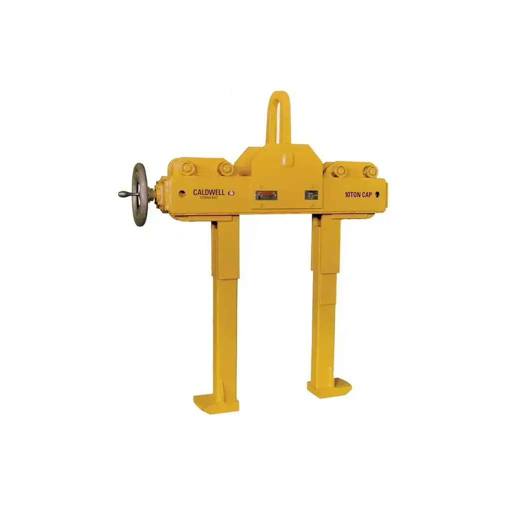
Caldwell Model BWC Beam Web Clamp — 67-1404
Caldwell Model BWC Beam Web Clamp — Multi-Angle I-Beam Lifting for Side and Top Load Applications
The Caldwell Model BWC Beam Web Clamp is a heavy-duty rigging tool engineered specifically for lifting and suspending I-beams during construction and structural steel erection. During both side-load and top-load applications, the clamp simultaneously grips the I-beam's web while pinching the flange, creating positive contact that prevents slippage at any lifting angle. Designed for contractors, ironworkers, and rigging crews, it is rated to full capacity regardless of the angle at which force is applied. The Model BWC complies with ASME B30.20 and BTH-1 standards, making it appropriate for regulated jobsite use.
Unlike conventional beam clamps that are limited to vertical top-load applications, the BWC is purpose-built to accommodate side-load scenarios — a critical advantage when maneuvering structural beams in tight or complex framing situations. Its low-headroom design allows use in overhead-restricted environments where standard rigging hardware would not fit, and its dual-contact gripping mechanism eliminates the need for additional securing hardware during lifts.
Key Features & Benefits
Side Load Accommodation
Most beam clamps are rated only for vertical top-load applications. The Model BWC is specifically engineered to handle side-load scenarios, giving rigging crews the flexibility to orient lifts based on field conditions rather than hardware limitations. This makes it essential for structural steel placement in complex framing layouts.
Full Rated Capacity at Any Lifting Angle
The BWC delivers its full rated capacity regardless of lifting angle — whether the load comes from directly above or from the side. This means crews do not need to derate the clamp or select oversized hardware to compensate for angled pulls, reducing cost and simplifying load planning.
Simultaneous Web and Flange Gripping
The clamp securely grabs both the beam web and flange at the same time, providing dual-point positive contact. This dual-grip mechanism significantly reduces the risk of beam slip during lifts and suspensions, a critical safety factor when working with heavy structural members overhead.
Low-Headroom Design
In jobsite environments where overhead clearance is limited — such as under existing floors, inside building cores, or beneath bridge decks — the BWC's low-headroom profile allows productive operation where taller rigging assemblies would be impractical or unsafe. This directly reduces the need for costly rigging workarounds.
Dual-Purpose Use: Lifting and Hanging
Beyond active lifts, the Model BWC can be used to suspend or hang loads from I-beams, making it useful for temporary support during assembly operations. This versatility means a single piece of hardware serves multiple roles on the jobsite.
ASME B30.20 and BTH-1 Compliance
Compliance with ASME B30.20 (Below-the-Hook Lifting Devices) and BTH-1 (Design of Below-the-Hook Lifting Devices) ensures the clamp meets recognized industry safety and design standards. This is a requirement on many commercial, industrial, and government construction projects, and simplifies jobsite safety inspections and documentation.
Common Applications
Structural Steel Erection
The Model BWC is ideally suited for lifting and placing I-beams during structural steel framing, where beams must often be moved horizontally or at angles before being set in final position.
Bridge Construction and Repair
Bridge decks and girder systems frequently require side-load lifting of heavy steel members in restricted-clearance environments — exactly the conditions the BWC is designed to handle.
Industrial Plant Construction
In manufacturing facilities and heavy industrial plants, structural beams are routinely set in congested overhead areas where low headroom and side-access are the only practical rigging options.
Beam Suspension and Temporary Support
The BWC can hold I-beams in suspended positions during assembly or welding operations, serving as a temporary holding device without requiring separate rigging setups.
Precast and Prefabricated Steel Assembly
When assembling prefabricated steel frames or modules in a fabrication yard or on-site, the BWC provides consistent, repeatable grip on standard I-beam profiles for efficient handling.
Overhead Crane and Hoist Operations
Compatible with standard bail connections used on overhead cranes and chain hoists, the BWC integrates directly into existing rigging setups without additional hardware.
Compatible Materials
- Standard wide-flange I-beams (W-shapes)
- S-shape (standard) I-beams
- Structural steel I-beams with flange widths from 6 in. to 15.75 in. (depending on model)
- I-beams with web configurations compatible with BWC-5, BWC-10, and BWC-10W models
Available Models
| Model | Rated Capacity (lbs.) | A - Max Width (in.) | B - Bail Opening (in.) | C - Body Thickness (in.) | D - Pin Length (in.) | E - Web Clearance (in.) | F - Headroom (in.) | G - Flange Clearance (in.) | H - Min Flange Width (in.) | H - Max Flange Width (in.) | Weight (lbs.) | Best For |
|---|---|---|---|---|---|---|---|---|---|---|---|---|
| BWC-5 | 11,200 | 20.50 | 2.75 | 3.00 | 3.50 | 1.25 | 4.50 | 1.00 | 6.00 | 12.00 | 76 | Medium-duty structural lifts up to 5.6 tons on standard-width flanges |
| BWC-10 | 22,400 | 20.50 | 2.75 | 3.00 | 3.50 | 1.25 | 4.50 | 1.00 | 6.00 | 12.00 | 76 | Heavy-duty structural lifts up to 11.2 tons on standard-width flanges |
| BWC-10W | 22,400 | 24.30 | 2.75 | 3.00 | 3.50 | 1.25 | 4.50 | 1.00 | 9.00 | 15.75 | 82 | Heavy-duty structural lifts up to 11.2 tons on wide-flange beams up to 15.75 in. |
Product Documents
Technical Specifications
| Specification | Details |
|---|---|
| Model Series | BWC (Beam Web Clamp) |
| Rated Capacity — BWC-5 | 11,200 lbs. (5.6 tons) |
| Rated Capacity — BWC-10 / BWC-10W | 22,400 lbs. (11.2 tons) |
| A - Max Width — BWC-5 / BWC-10 | 20.50 in. |
| A - Max Width — BWC-10W | 24.30 in. |
| B - Bail Opening | 2.75 in. (all models) |
| C - Body Thickness | 3.00 in. (all models) |
| D - Pin Length | 3.50 in. (all models) |
| E - Web Clearance | 1.25 in. (all models) |
| F - Headroom | 4.50 in. (all models) |
| G - Flange Clearance | 1.00 in. (all models) |
| H - Min Flange Width — BWC-5 / BWC-10 | 6.00 in. |
| H - Max Flange Width — BWC-5 / BWC-10 | 12.00 in. |
| H - Min Flange Width — BWC-10W | 9.00 in. |
| H - Max Flange Width — BWC-10W | 15.75 in. |
| Weight — BWC-5 / BWC-10 | 76 lbs. |
| Weight — BWC-10W | 82 lbs. |
| Compliance Standards | ASME B30.20, BTH-1 |
| Lifting Angle Rating | Full rated capacity at any lifting angle |
| Load Application Types | Side-load and top-load |
| Grip Mechanism | Simultaneous web grip and flange pinch |
| Headroom Profile | Low-headroom design (4.50 in. headroom) |
| Compatible Beam Types | Standard I-beams and wide-flange (W-shape) beams |
Frequently Asked Questions
Q: Can the Model BWC be used for side-load lifts, or is it only rated for vertical top-load applications?
A: The BWC is specifically designed to accommodate side-load applications and maintains its full rated capacity at any lifting angle, including side-load configurations. This is one of its primary differentiators from standard beam clamps.
Q: Does the rated capacity change based on the angle of the lift?
A: No. The Model BWC delivers full rated capacity at any lifting angle. There is no derating required for angled or side-load pulls.
Q: What flange width range does each model accommodate?
A: The BWC-5 and BWC-10 accommodate flange widths from 6.00 in. to 12.00 in. The BWC-10W is designed for wider flanges, accommodating 9.00 in. to 15.75 in. flange widths.
Q: Is the Model BWC suitable for suspending or hanging loads, or only for active lifts?
A: The BWC is rated for both lifting and hanging (suspension) applications, making it useful for temporary beam support during fabrication, assembly, and structural installation operations.
Q: What safety standards does the Model BWC comply with?
A: The Model BWC complies with ASME B30.20 (Below-the-Hook Lifting Devices) and BTH-1 (Design of Below-the-Hook Lifting Devices), meeting recognized national safety and design standards for below-the-hook rigging equipment.
Q: What is the difference between the BWC-10 and BWC-10W?
A: Both models share the same 22,400 lb. (11.2 ton) rated capacity, but the BWC-10W has a wider maximum body width (24.30 in. vs. 20.50 in.) and accommodates wider flanges — up to 15.75 in. versus 12.00 in. for the BWC-10. The BWC-10W also weighs slightly more at 82 lbs. versus 76 lbs.
Product Information
Product Information
Shipping & Returns
Shipping & Returns


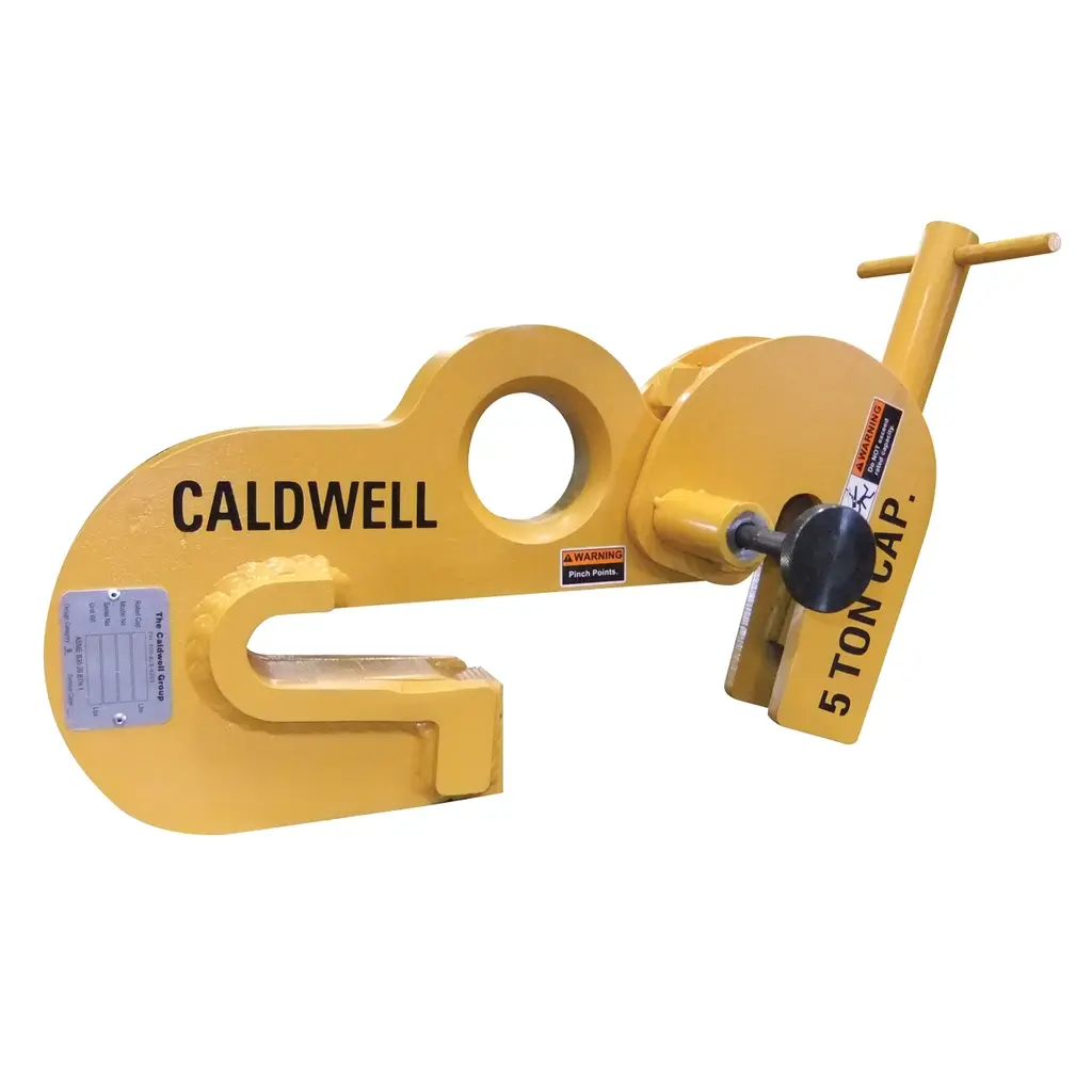


Caldwell Model BWC Beam Web Clamp — 67-1404
Caldwell Model BWC Beam Web Clamp — 67-1404
Caldwell Model BWC Beam Web Clamp — Multi-Angle I-Beam Lifting for Side and Top Load Applications
The Caldwell Model BWC Beam Web Clamp is a heavy-duty rigging tool engineered specifically for lifting and suspending I-beams during construction and structural steel erection. During both side-load and top-load applications, the clamp simultaneously grips the I-beam's web while pinching the flange, creating positive contact that prevents slippage at any lifting angle. Designed for contractors, ironworkers, and rigging crews, it is rated to full capacity regardless of the angle at which force is applied. The Model BWC complies with ASME B30.20 and BTH-1 standards, making it appropriate for regulated jobsite use.
Unlike conventional beam clamps that are limited to vertical top-load applications, the BWC is purpose-built to accommodate side-load scenarios — a critical advantage when maneuvering structural beams in tight or complex framing situations. Its low-headroom design allows use in overhead-restricted environments where standard rigging hardware would not fit, and its dual-contact gripping mechanism eliminates the need for additional securing hardware during lifts.
Key Features & Benefits
Side Load Accommodation
Most beam clamps are rated only for vertical top-load applications. The Model BWC is specifically engineered to handle side-load scenarios, giving rigging crews the flexibility to orient lifts based on field conditions rather than hardware limitations. This makes it essential for structural steel placement in complex framing layouts.
Full Rated Capacity at Any Lifting Angle
The BWC delivers its full rated capacity regardless of lifting angle — whether the load comes from directly above or from the side. This means crews do not need to derate the clamp or select oversized hardware to compensate for angled pulls, reducing cost and simplifying load planning.
Simultaneous Web and Flange Gripping
The clamp securely grabs both the beam web and flange at the same time, providing dual-point positive contact. This dual-grip mechanism significantly reduces the risk of beam slip during lifts and suspensions, a critical safety factor when working with heavy structural members overhead.
Low-Headroom Design
In jobsite environments where overhead clearance is limited — such as under existing floors, inside building cores, or beneath bridge decks — the BWC's low-headroom profile allows productive operation where taller rigging assemblies would be impractical or unsafe. This directly reduces the need for costly rigging workarounds.
Dual-Purpose Use: Lifting and Hanging
Beyond active lifts, the Model BWC can be used to suspend or hang loads from I-beams, making it useful for temporary support during assembly operations. This versatility means a single piece of hardware serves multiple roles on the jobsite.
ASME B30.20 and BTH-1 Compliance
Compliance with ASME B30.20 (Below-the-Hook Lifting Devices) and BTH-1 (Design of Below-the-Hook Lifting Devices) ensures the clamp meets recognized industry safety and design standards. This is a requirement on many commercial, industrial, and government construction projects, and simplifies jobsite safety inspections and documentation.
Common Applications
Structural Steel Erection
The Model BWC is ideally suited for lifting and placing I-beams during structural steel framing, where beams must often be moved horizontally or at angles before being set in final position.
Bridge Construction and Repair
Bridge decks and girder systems frequently require side-load lifting of heavy steel members in restricted-clearance environments — exactly the conditions the BWC is designed to handle.
Industrial Plant Construction
In manufacturing facilities and heavy industrial plants, structural beams are routinely set in congested overhead areas where low headroom and side-access are the only practical rigging options.
Beam Suspension and Temporary Support
The BWC can hold I-beams in suspended positions during assembly or welding operations, serving as a temporary holding device without requiring separate rigging setups.
Precast and Prefabricated Steel Assembly
When assembling prefabricated steel frames or modules in a fabrication yard or on-site, the BWC provides consistent, repeatable grip on standard I-beam profiles for efficient handling.
Overhead Crane and Hoist Operations
Compatible with standard bail connections used on overhead cranes and chain hoists, the BWC integrates directly into existing rigging setups without additional hardware.
Compatible Materials
- Standard wide-flange I-beams (W-shapes)
- S-shape (standard) I-beams
- Structural steel I-beams with flange widths from 6 in. to 15.75 in. (depending on model)
- I-beams with web configurations compatible with BWC-5, BWC-10, and BWC-10W models
Available Models
| Model | Rated Capacity (lbs.) | A - Max Width (in.) | B - Bail Opening (in.) | C - Body Thickness (in.) | D - Pin Length (in.) | E - Web Clearance (in.) | F - Headroom (in.) | G - Flange Clearance (in.) | H - Min Flange Width (in.) | H - Max Flange Width (in.) | Weight (lbs.) | Best For |
|---|---|---|---|---|---|---|---|---|---|---|---|---|
| BWC-5 | 11,200 | 20.50 | 2.75 | 3.00 | 3.50 | 1.25 | 4.50 | 1.00 | 6.00 | 12.00 | 76 | Medium-duty structural lifts up to 5.6 tons on standard-width flanges |
| BWC-10 | 22,400 | 20.50 | 2.75 | 3.00 | 3.50 | 1.25 | 4.50 | 1.00 | 6.00 | 12.00 | 76 | Heavy-duty structural lifts up to 11.2 tons on standard-width flanges |
| BWC-10W | 22,400 | 24.30 | 2.75 | 3.00 | 3.50 | 1.25 | 4.50 | 1.00 | 9.00 | 15.75 | 82 | Heavy-duty structural lifts up to 11.2 tons on wide-flange beams up to 15.75 in. |
Product Documents
Technical Specifications
| Specification | Details |
|---|---|
| Model Series | BWC (Beam Web Clamp) |
| Rated Capacity — BWC-5 | 11,200 lbs. (5.6 tons) |
| Rated Capacity — BWC-10 / BWC-10W | 22,400 lbs. (11.2 tons) |
| A - Max Width — BWC-5 / BWC-10 | 20.50 in. |
| A - Max Width — BWC-10W | 24.30 in. |
| B - Bail Opening | 2.75 in. (all models) |
| C - Body Thickness | 3.00 in. (all models) |
| D - Pin Length | 3.50 in. (all models) |
| E - Web Clearance | 1.25 in. (all models) |
| F - Headroom | 4.50 in. (all models) |
| G - Flange Clearance | 1.00 in. (all models) |
| H - Min Flange Width — BWC-5 / BWC-10 | 6.00 in. |
| H - Max Flange Width — BWC-5 / BWC-10 | 12.00 in. |
| H - Min Flange Width — BWC-10W | 9.00 in. |
| H - Max Flange Width — BWC-10W | 15.75 in. |
| Weight — BWC-5 / BWC-10 | 76 lbs. |
| Weight — BWC-10W | 82 lbs. |
| Compliance Standards | ASME B30.20, BTH-1 |
| Lifting Angle Rating | Full rated capacity at any lifting angle |
| Load Application Types | Side-load and top-load |
| Grip Mechanism | Simultaneous web grip and flange pinch |
| Headroom Profile | Low-headroom design (4.50 in. headroom) |
| Compatible Beam Types | Standard I-beams and wide-flange (W-shape) beams |
Frequently Asked Questions
Q: Can the Model BWC be used for side-load lifts, or is it only rated for vertical top-load applications?
A: The BWC is specifically designed to accommodate side-load applications and maintains its full rated capacity at any lifting angle, including side-load configurations. This is one of its primary differentiators from standard beam clamps.
Q: Does the rated capacity change based on the angle of the lift?
A: No. The Model BWC delivers full rated capacity at any lifting angle. There is no derating required for angled or side-load pulls.
Q: What flange width range does each model accommodate?
A: The BWC-5 and BWC-10 accommodate flange widths from 6.00 in. to 12.00 in. The BWC-10W is designed for wider flanges, accommodating 9.00 in. to 15.75 in. flange widths.
Q: Is the Model BWC suitable for suspending or hanging loads, or only for active lifts?
A: The BWC is rated for both lifting and hanging (suspension) applications, making it useful for temporary beam support during fabrication, assembly, and structural installation operations.
Q: What safety standards does the Model BWC comply with?
A: The Model BWC complies with ASME B30.20 (Below-the-Hook Lifting Devices) and BTH-1 (Design of Below-the-Hook Lifting Devices), meeting recognized national safety and design standards for below-the-hook rigging equipment.
Q: What is the difference between the BWC-10 and BWC-10W?
A: Both models share the same 22,400 lb. (11.2 ton) rated capacity, but the BWC-10W has a wider maximum body width (24.30 in. vs. 20.50 in.) and accommodates wider flanges — up to 15.75 in. versus 12.00 in. for the BWC-10. The BWC-10W also weighs slightly more at 82 lbs. versus 76 lbs.
Original: $4,094.00
-65%$4,094.00
$1,432.90Product Information
Product Information
Shipping & Returns
Shipping & Returns
Description
Caldwell Model BWC Beam Web Clamp — Multi-Angle I-Beam Lifting for Side and Top Load Applications
The Caldwell Model BWC Beam Web Clamp is a heavy-duty rigging tool engineered specifically for lifting and suspending I-beams during construction and structural steel erection. During both side-load and top-load applications, the clamp simultaneously grips the I-beam's web while pinching the flange, creating positive contact that prevents slippage at any lifting angle. Designed for contractors, ironworkers, and rigging crews, it is rated to full capacity regardless of the angle at which force is applied. The Model BWC complies with ASME B30.20 and BTH-1 standards, making it appropriate for regulated jobsite use.
Unlike conventional beam clamps that are limited to vertical top-load applications, the BWC is purpose-built to accommodate side-load scenarios — a critical advantage when maneuvering structural beams in tight or complex framing situations. Its low-headroom design allows use in overhead-restricted environments where standard rigging hardware would not fit, and its dual-contact gripping mechanism eliminates the need for additional securing hardware during lifts.
Key Features & Benefits
Side Load Accommodation
Most beam clamps are rated only for vertical top-load applications. The Model BWC is specifically engineered to handle side-load scenarios, giving rigging crews the flexibility to orient lifts based on field conditions rather than hardware limitations. This makes it essential for structural steel placement in complex framing layouts.
Full Rated Capacity at Any Lifting Angle
The BWC delivers its full rated capacity regardless of lifting angle — whether the load comes from directly above or from the side. This means crews do not need to derate the clamp or select oversized hardware to compensate for angled pulls, reducing cost and simplifying load planning.
Simultaneous Web and Flange Gripping
The clamp securely grabs both the beam web and flange at the same time, providing dual-point positive contact. This dual-grip mechanism significantly reduces the risk of beam slip during lifts and suspensions, a critical safety factor when working with heavy structural members overhead.
Low-Headroom Design
In jobsite environments where overhead clearance is limited — such as under existing floors, inside building cores, or beneath bridge decks — the BWC's low-headroom profile allows productive operation where taller rigging assemblies would be impractical or unsafe. This directly reduces the need for costly rigging workarounds.
Dual-Purpose Use: Lifting and Hanging
Beyond active lifts, the Model BWC can be used to suspend or hang loads from I-beams, making it useful for temporary support during assembly operations. This versatility means a single piece of hardware serves multiple roles on the jobsite.
ASME B30.20 and BTH-1 Compliance
Compliance with ASME B30.20 (Below-the-Hook Lifting Devices) and BTH-1 (Design of Below-the-Hook Lifting Devices) ensures the clamp meets recognized industry safety and design standards. This is a requirement on many commercial, industrial, and government construction projects, and simplifies jobsite safety inspections and documentation.
Common Applications
Structural Steel Erection
The Model BWC is ideally suited for lifting and placing I-beams during structural steel framing, where beams must often be moved horizontally or at angles before being set in final position.
Bridge Construction and Repair
Bridge decks and girder systems frequently require side-load lifting of heavy steel members in restricted-clearance environments — exactly the conditions the BWC is designed to handle.
Industrial Plant Construction
In manufacturing facilities and heavy industrial plants, structural beams are routinely set in congested overhead areas where low headroom and side-access are the only practical rigging options.
Beam Suspension and Temporary Support
The BWC can hold I-beams in suspended positions during assembly or welding operations, serving as a temporary holding device without requiring separate rigging setups.
Precast and Prefabricated Steel Assembly
When assembling prefabricated steel frames or modules in a fabrication yard or on-site, the BWC provides consistent, repeatable grip on standard I-beam profiles for efficient handling.
Overhead Crane and Hoist Operations
Compatible with standard bail connections used on overhead cranes and chain hoists, the BWC integrates directly into existing rigging setups without additional hardware.
Compatible Materials
- Standard wide-flange I-beams (W-shapes)
- S-shape (standard) I-beams
- Structural steel I-beams with flange widths from 6 in. to 15.75 in. (depending on model)
- I-beams with web configurations compatible with BWC-5, BWC-10, and BWC-10W models
Available Models
| Model | Rated Capacity (lbs.) | A - Max Width (in.) | B - Bail Opening (in.) | C - Body Thickness (in.) | D - Pin Length (in.) | E - Web Clearance (in.) | F - Headroom (in.) | G - Flange Clearance (in.) | H - Min Flange Width (in.) | H - Max Flange Width (in.) | Weight (lbs.) | Best For |
|---|---|---|---|---|---|---|---|---|---|---|---|---|
| BWC-5 | 11,200 | 20.50 | 2.75 | 3.00 | 3.50 | 1.25 | 4.50 | 1.00 | 6.00 | 12.00 | 76 | Medium-duty structural lifts up to 5.6 tons on standard-width flanges |
| BWC-10 | 22,400 | 20.50 | 2.75 | 3.00 | 3.50 | 1.25 | 4.50 | 1.00 | 6.00 | 12.00 | 76 | Heavy-duty structural lifts up to 11.2 tons on standard-width flanges |
| BWC-10W | 22,400 | 24.30 | 2.75 | 3.00 | 3.50 | 1.25 | 4.50 | 1.00 | 9.00 | 15.75 | 82 | Heavy-duty structural lifts up to 11.2 tons on wide-flange beams up to 15.75 in. |
Product Documents
Technical Specifications
| Specification | Details |
|---|---|
| Model Series | BWC (Beam Web Clamp) |
| Rated Capacity — BWC-5 | 11,200 lbs. (5.6 tons) |
| Rated Capacity — BWC-10 / BWC-10W | 22,400 lbs. (11.2 tons) |
| A - Max Width — BWC-5 / BWC-10 | 20.50 in. |
| A - Max Width — BWC-10W | 24.30 in. |
| B - Bail Opening | 2.75 in. (all models) |
| C - Body Thickness | 3.00 in. (all models) |
| D - Pin Length | 3.50 in. (all models) |
| E - Web Clearance | 1.25 in. (all models) |
| F - Headroom | 4.50 in. (all models) |
| G - Flange Clearance | 1.00 in. (all models) |
| H - Min Flange Width — BWC-5 / BWC-10 | 6.00 in. |
| H - Max Flange Width — BWC-5 / BWC-10 | 12.00 in. |
| H - Min Flange Width — BWC-10W | 9.00 in. |
| H - Max Flange Width — BWC-10W | 15.75 in. |
| Weight — BWC-5 / BWC-10 | 76 lbs. |
| Weight — BWC-10W | 82 lbs. |
| Compliance Standards | ASME B30.20, BTH-1 |
| Lifting Angle Rating | Full rated capacity at any lifting angle |
| Load Application Types | Side-load and top-load |
| Grip Mechanism | Simultaneous web grip and flange pinch |
| Headroom Profile | Low-headroom design (4.50 in. headroom) |
| Compatible Beam Types | Standard I-beams and wide-flange (W-shape) beams |
Frequently Asked Questions
Q: Can the Model BWC be used for side-load lifts, or is it only rated for vertical top-load applications?
A: The BWC is specifically designed to accommodate side-load applications and maintains its full rated capacity at any lifting angle, including side-load configurations. This is one of its primary differentiators from standard beam clamps.
Q: Does the rated capacity change based on the angle of the lift?
A: No. The Model BWC delivers full rated capacity at any lifting angle. There is no derating required for angled or side-load pulls.
Q: What flange width range does each model accommodate?
A: The BWC-5 and BWC-10 accommodate flange widths from 6.00 in. to 12.00 in. The BWC-10W is designed for wider flanges, accommodating 9.00 in. to 15.75 in. flange widths.
Q: Is the Model BWC suitable for suspending or hanging loads, or only for active lifts?
A: The BWC is rated for both lifting and hanging (suspension) applications, making it useful for temporary beam support during fabrication, assembly, and structural installation operations.
Q: What safety standards does the Model BWC comply with?
A: The Model BWC complies with ASME B30.20 (Below-the-Hook Lifting Devices) and BTH-1 (Design of Below-the-Hook Lifting Devices), meeting recognized national safety and design standards for below-the-hook rigging equipment.
Q: What is the difference between the BWC-10 and BWC-10W?
A: Both models share the same 22,400 lb. (11.2 ton) rated capacity, but the BWC-10W has a wider maximum body width (24.30 in. vs. 20.50 in.) and accommodates wider flanges — up to 15.75 in. versus 12.00 in. for the BWC-10. The BWC-10W also weighs slightly more at 82 lbs. versus 76 lbs.