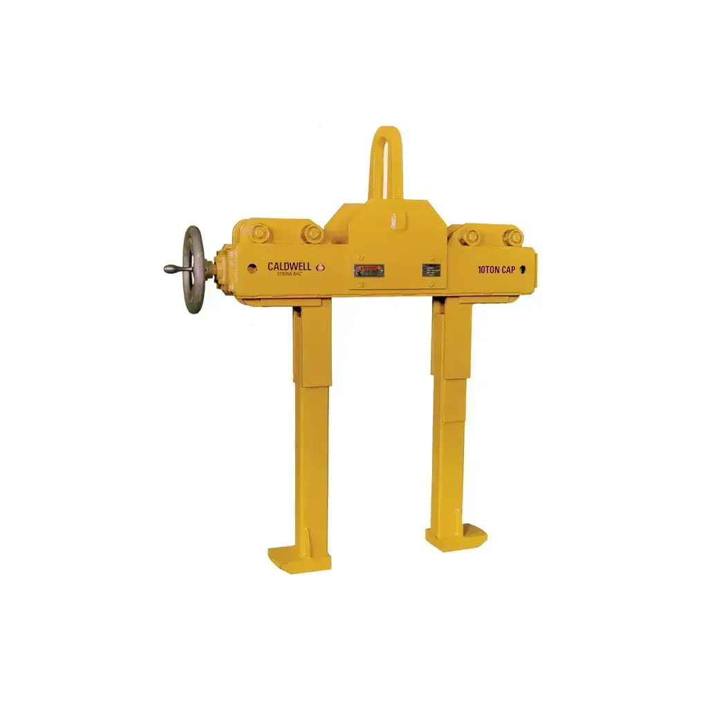
Caldwell BFC Beam Flange Clamp 1–11 Ton
Caldwell Model BFC Beam Flange Clamps — Versatile Overhead Rigging for 1 to 10 Metric Ton Loads
The Caldwell Model BFC Beam Flange Clamp is a heavy-duty, portable clamping solution engineered for contractors and riggers who need reliable, code-compliant attachment to structural beam flanges. Available in five rated capacity configurations ranging from 1.1 tons (2,200 lbs.) to 11 tons (22,000 lbs.), the BFC series gives crews the flexibility to match the clamp to the job rather than working around equipment limitations. The clamp attaches directly to the flange of a structural steel I-beam or wide-flange section, enabling users to hang hoists, attach rigging, or lift and position structural members from an overhead load-bearing structure. Each unit ships proof-tested with a certificate, meeting ASME B30.20 and BTH-1 standards right out of the box.
Unlike fixed-jaw or pin-style beam clamps that require a specific flange width, the BFC uses a left-hand and right-hand thread screw spindle that allows fast, tool-free clamping and unclamping across a range of flange thicknesses. A built-in lock nut prevents inadvertent loosening under dynamic load, and the integrated suspension pin reduces headroom loss compared to add-on hook arrangements — a meaningful advantage in tight overhead clearance environments. Used in pairs with a spreader beam, the BFC handles significantly larger structural members than a single clamp, making it a multi-role tool for steel erection and rigging operations.
Key Features & Benefits
Five Capacity Options (1 to 10 Metric Tons)
Selecting the right rated capacity reduces unnecessary weight on the job and ensures the clamp is not over-stressed. With models spanning 2,200 lbs. to 22,000 lbs., contractors can spec the correct unit for each lift rather than defaulting to an oversized clamp that adds bulk and cost. All five models share the same proven design architecture, so crews already familiar with one size can operate any other in the range without additional training.
Left-Hand / Right-Hand Thread Screw Spindle
The dual-thread screw spindle design means the jaws open and close at twice the speed of a conventional single-thread spindle, significantly cutting setup time across repeated lifts. Rapid clamping and unclamping is especially valuable in steel erection work where the clamp is repositioned frequently throughout the shift. Less time per attachment cycle translates directly to higher productivity on multi-piece structural jobs.
Lock Nut for Secure Load Retention
The integrated lock nut locks the screw spindle in place after the clamp is seated on the flange, preventing the jaws from backing off under vibration, dynamic loading, or incidental contact. This is a critical safety feature in overhead rigging where inadvertent loosening can result in dropped loads. Crews can work with confidence that a properly set clamp will not self-release during the lift cycle.
Built-In Suspension Pin for Reduced Headroom Loss
The suspension pin is integrated directly into the clamp body, eliminating the need to thread a separate hook or shackle through the bail before making the hoist connection. This reduces the total hook-to-beam distance, preserving usable hook height in low-clearance bays, mezzanines, and tight structural steel environments. Lower headroom requirements allow the clamp to be used in applications where competing products would simply not fit.
Proof Tested with Certificate
Every BFC clamp is individually proof tested before shipment, and a test certificate is included. This satisfies documentation requirements on regulated job sites and for safety-audited contractors without requiring third-party inspection. The certificate provides traceability and confirms the clamp has been verified at a load above its rated capacity prior to first use.
Optional Large Bail for Oversized Hoist Hooks
The Large Bail (Option LB) upgrade accommodates oversized hoist hooks that do not fit through a standard bail opening, eliminating the need for an intermediate shackle that adds cost, connection points, and headroom. This option is available across the full BFC range and is specified at time of order by selecting the LB-suffix model number. It is particularly relevant when using large-capacity chain hoists or wire rope hoists with thicker hooks.
ASME B30.20 and BTH-1 Compliance
Compliance with ASME B30.20 (Below-the-Hook Lifting Devices) and BTH-1 (Design of Below-the-Hook Lifting Devices), along with a 5:1 design factor meeting portions of ASME B30.16, ensures the BFC meets the standards required by most general contractors, structural steel fabricators, and safety inspectors. Using non-compliant lifting hardware is a common source of OSHA citations; the BFC removes that risk from the equation.
Common Applications
Hanging Chain Hoists and Wire Rope Hoists from Structural Steel
The BFC's primary application is providing a secure, repositionable attachment point for electric or manual hoists on structural I-beams and wide-flange sections where a permanent trolley or monorail is not installed. The clamp can be moved along the beam and repositioned to align the hoist with the load pick point.
Overhead Rigging Attachment Points
Riggers use the BFC to establish attachment points on overhead structural steel for block-and-tackle arrangements, come-alongs, and multi-leg sling configurations. The suspension pin and optional large bail support a wide variety of rigging hardware connection types.
Lifting and Positioning Structural Steel Beams
When used in pairs with a spreader beam, BFC clamps allow crews to lift and position structural steel beams horizontally, controlling both pick points simultaneously. This is the standard technique for setting wide-flange beams during steel erection without damaging the member's flanges or web.
Temporary Load Points During Construction
On active construction sites where permanent crane rails or monorails are not yet installed, the BFC creates immediate temporary lifting infrastructure on any accessible structural beam. This allows mechanical, electrical, and plumbing trades to move equipment into position before permanent material handling systems are commissioned.
Industrial Maintenance and Equipment Setting
Plant maintenance crews use beam flange clamps to set machinery, lift motors, and position heavy components using existing overhead structure rather than renting mobile cranes or setting up temporary gantries. The BFC's powder-coat finish and portable weight make it well-suited for repeated use in industrial maintenance environments.
Spreader Beam Rigging in Pairs
Two BFC clamps used in conjunction with a spreader beam distribute the load across two pick points on an overhead beam, enabling lifts of significantly larger and heavier structural members than a single clamp would permit. This configuration is common in bridge, heavy industrial, and large commercial structural steel applications.
Compatible Materials
- Structural steel I-beams (S-shapes)
- Wide-flange (W-shape) structural steel beams
- Standard and heavy wide-flange sections within specified flange thickness limits
- Overhead load-bearing structural steel within rated flange thickness range per model
- Spreader beam top flanges (when used in paired rigging configurations)
Available Models
| Model Number | Rated Capacity | D Min (in.) | D Max (in.) | E Max (in.) | F (in.) | G (in.) | H Dia. (in.) | J (in.) | Max Flange Thickness (in.) | Weight (lbs.) | Best For |
|---|---|---|---|---|---|---|---|---|---|---|---|
| BFC-1-C | 1.1 tons / 2,200 lbs. | 3.00 | 7.50 | 12.25 | 3.00 | 9.25 | 0.88 | 2.10 | 0.83 | 8 | Light-duty hoist hanging and rigging on smaller structural sections |
| BFC-2-C | 2.2 tons / 4,400 lbs. | 3.00 | 7.50 | 12.25 | 3.00 | 9.25 | 0.88 | 2.10 | 0.83 | 9 | Mid-range hoisting and positioning on standard structural beams |
| BFC-3-C | 3.3 tons / 6,600 lbs. | 6.00 | 12.00 | 19.75 | 4.25 | 11.00 | 1.25 | 2.38 | 1.00 | 19 | Heavy hoist support and structural beam lifting on medium sections |
| BFC-5-C | 5.5 tons / 11,000 lbs. | 6.00 | 12.00 | 19.75 | 4.25 | 11.00 | 1.25 | 2.38 | 1.00 | 22 | Heavy structural steel erection and paired spreader beam rigging |
| BFC-10-C | 11 tons / 22,000 lbs. | 6.00 | 13.25 | 22.50 | 6.00 | 14.63 | 1.75 | 4.65 | 1.25 | 50 | Maximum-capacity heavy industrial lifts and large structural steel positioning |
Product Documents
Technical Specifications
| Specification | Details |
|---|---|
| Capacity Range | 1.1 to 11 metric tons (2,200 to 22,000 lbs.) |
| Number of Capacity Options | 5 models (BFC-1-C through BFC-10-C) |
| Design Factor | 5:1 (meets portions of ASME B30.16) |
| Standards Compliance | ASME B30.20, BTH-1 |
| Proof Test | Yes — individual proof test with certificate included |
| Finish | Powder-coat |
| Screw Spindle Type | Left-hand and right-hand thread (dual thread for rapid operation) |
| Lock Nut | Yes — prevents inadvertent loosening |
| Suspension Pin | Built-in (reduces headroom requirement) |
| Large Bail Option | Available on all models (suffix: LB) for oversized hoist hooks |
| BFC-1-C D Min | 3.00 in. |
| BFC-1-C D Max | 7.50 in. |
| BFC-1-C E Max | 12.25 in. |
| BFC-1-C Dimension F | 3.00 in. |
| BFC-1-C Dimension G | 9.25 in. |
| BFC-1-C H Diameter | 0.88 in. |
| BFC-1-C Dimension J | 2.10 in. |
| BFC-1-C Max Flange Thickness | 0.83 in. |
| BFC-1-C Weight | 8 lbs. |
| BFC-2-C D Min | 3.00 in. |
| BFC-2-C D Max | 7.50 in. |
| BFC-2-C E Max | 12.25 in. |
| BFC-2-C Dimension F | 3.00 in. |
| BFC-2-C Dimension G | 9.25 in. |
| BFC-2-C H Diameter | 0.88 in. |
| BFC-2-C Dimension J | 2.10 in. |
| BFC-2-C Max Flange Thickness | 0.83 in. |
| BFC-2-C Weight | 9 lbs. |
| BFC-3-C D Min | 6.00 in. |
| BFC-3-C D Max | 12.00 in. |
| BFC-3-C E Max | 19.75 in. |
| BFC-3-C Dimension F | 4.25 in. |
| BFC-3-C Dimension G | 11.00 in. |
| BFC-3-C H Diameter | 1.25 in. |
| BFC-3-C Dimension J | 2.38 in. |
| BFC-3-C Max Flange Thickness | 1.00 in. |
| BFC-3-C Weight | 19 lbs. |
| BFC-5-C D Min | 6.00 in. |
| BFC-5-C D Max | 12.00 in. |
| BFC-5-C E Max | 19.75 in. |
| BFC-5-C Dimension F | 4.25 in. |
| BFC-5-C Dimension G | 11.00 in. |
| BFC-5-C H Diameter | 1.25 in. |
| BFC-5-C Dimension J | 2.38 in. |
| BFC-5-C Max Flange Thickness | 1.00 in. |
| BFC-5-C Weight | 22 lbs. |
| BFC-10-C D Min | 6.00 in. |
| BFC-10-C D Max | 13.25 in. |
| BFC-10-C E Max | 22.50 in. |
| BFC-10-C Dimension F | 6.00 in. |
| BFC-10-C Dimension G | 14.63 in. |
| BFC-10-C H Diameter | 1.75 in. |
| BFC-10-C Dimension J | 4.65 in. |
| BFC-10-C Max Flange Thickness | 1.25 in. |
| BFC-10-C Weight | 50 lbs. |
| Option LB (Large Bail) — A | 0.75 in. (BFC-1-C / BFC-2-C); 1.00 in. (BFC-3-C / BFC-5-C); 1.38 in. (BFC-10-C) |
| Option LB (Large Bail) — B | 2.00 in. (BFC-1-C / BFC-2-C); 2.50 in. (BFC-3-C / BFC-5-C); 3.75 in. (BFC-10-C) |
| Option LB (Large Bail) — C | 2.00 in. (BFC-1-C / BFC-2-C); 2.50 in. (BFC-3-C / BFC-5-C); 6.25 in. (BFC-10-C) |
| Option LB (Large Bail) — T | 0.63 in. (BFC-1-C / BFC-2-C); 1.00 in. (BFC-3-C / BFC-5-C); 1.25 in. (BFC-10-C) |
| HR Min (BFC-1-C / BFC-2-C) | 3 in. |
| HR Max (BFC-1-C / BFC-2-C) | 5 in. |
Frequently Asked Questions
Q: Can the BFC clamp be used on any structural steel beam size?
A: The BFC is designed for use on beams whose flange width and thickness fall within the specified D Min, D Max, and maximum flange thickness dimensions for the selected model. Verify the beam's flange dimensions against the spec table before selecting a model — using a clamp outside its rated dimensional range can result in an insecure connection.
Q: Does the BFC clamp come with a proof test certificate?
A: Yes. Every Model BFC is individually proof tested prior to shipment, and a proof test certificate is included with each unit. This satisfies documentation and traceability requirements on audited construction and industrial job sites.
Q: Can two BFC clamps be used together with a spreader beam?
A: Yes. Using BFC clamps in pairs in conjunction with a spreader beam is an explicitly supported application. This configuration distributes the load across two attachment points and allows crews to lift and position larger structural members than would be possible with a single clamp. Ensure that each clamp in the pair is rated for at least half of the total load.
Q: What is the Large Bail (Option LB) and when is it needed?
A: The Large Bail option replaces the standard bail with an oversized version that accommodates hoist hooks too large to fit through a standard bail opening. This is typically required with large-capacity chain hoists or wire rope hoists. It eliminates the need for an intermediate shackle, reducing total hook-to-beam height and the number of connection points in the load path.
Q: Is the BFC clamp compliant with OSHA and industry standards?
A: The BFC complies with ASME B30.20 (Below-the-Hook Lifting Devices) and BTH-1 (Design of Below-the-Hook Lifting Devices), and its 5:1 design factor meets portions of ASME B30.16. These are the primary standards referenced by OSHA and general contractors for below-the-hook lifting hardware on regulated job sites.
Q: How do I select the correct BFC model for my application?
A: Select the model whose rated capacity meets or exceeds the maximum expected load, and verify that your beam's flange width falls between the D Min and D Max values and that the flange thickness does not exceed the maximum flange thickness listed for that model. If you are lifting with two clamps, each clamp must be rated for at least half the total suspended load.
Product Information
Product Information
Shipping & Returns
Shipping & Returns


Caldwell BFC Beam Flange Clamp 1–11 Ton
Caldwell BFC Beam Flange Clamp 1–11 Ton
Caldwell Model BFC Beam Flange Clamps — Versatile Overhead Rigging for 1 to 10 Metric Ton Loads
The Caldwell Model BFC Beam Flange Clamp is a heavy-duty, portable clamping solution engineered for contractors and riggers who need reliable, code-compliant attachment to structural beam flanges. Available in five rated capacity configurations ranging from 1.1 tons (2,200 lbs.) to 11 tons (22,000 lbs.), the BFC series gives crews the flexibility to match the clamp to the job rather than working around equipment limitations. The clamp attaches directly to the flange of a structural steel I-beam or wide-flange section, enabling users to hang hoists, attach rigging, or lift and position structural members from an overhead load-bearing structure. Each unit ships proof-tested with a certificate, meeting ASME B30.20 and BTH-1 standards right out of the box.
Unlike fixed-jaw or pin-style beam clamps that require a specific flange width, the BFC uses a left-hand and right-hand thread screw spindle that allows fast, tool-free clamping and unclamping across a range of flange thicknesses. A built-in lock nut prevents inadvertent loosening under dynamic load, and the integrated suspension pin reduces headroom loss compared to add-on hook arrangements — a meaningful advantage in tight overhead clearance environments. Used in pairs with a spreader beam, the BFC handles significantly larger structural members than a single clamp, making it a multi-role tool for steel erection and rigging operations.
Key Features & Benefits
Five Capacity Options (1 to 10 Metric Tons)
Selecting the right rated capacity reduces unnecessary weight on the job and ensures the clamp is not over-stressed. With models spanning 2,200 lbs. to 22,000 lbs., contractors can spec the correct unit for each lift rather than defaulting to an oversized clamp that adds bulk and cost. All five models share the same proven design architecture, so crews already familiar with one size can operate any other in the range without additional training.
Left-Hand / Right-Hand Thread Screw Spindle
The dual-thread screw spindle design means the jaws open and close at twice the speed of a conventional single-thread spindle, significantly cutting setup time across repeated lifts. Rapid clamping and unclamping is especially valuable in steel erection work where the clamp is repositioned frequently throughout the shift. Less time per attachment cycle translates directly to higher productivity on multi-piece structural jobs.
Lock Nut for Secure Load Retention
The integrated lock nut locks the screw spindle in place after the clamp is seated on the flange, preventing the jaws from backing off under vibration, dynamic loading, or incidental contact. This is a critical safety feature in overhead rigging where inadvertent loosening can result in dropped loads. Crews can work with confidence that a properly set clamp will not self-release during the lift cycle.
Built-In Suspension Pin for Reduced Headroom Loss
The suspension pin is integrated directly into the clamp body, eliminating the need to thread a separate hook or shackle through the bail before making the hoist connection. This reduces the total hook-to-beam distance, preserving usable hook height in low-clearance bays, mezzanines, and tight structural steel environments. Lower headroom requirements allow the clamp to be used in applications where competing products would simply not fit.
Proof Tested with Certificate
Every BFC clamp is individually proof tested before shipment, and a test certificate is included. This satisfies documentation requirements on regulated job sites and for safety-audited contractors without requiring third-party inspection. The certificate provides traceability and confirms the clamp has been verified at a load above its rated capacity prior to first use.
Optional Large Bail for Oversized Hoist Hooks
The Large Bail (Option LB) upgrade accommodates oversized hoist hooks that do not fit through a standard bail opening, eliminating the need for an intermediate shackle that adds cost, connection points, and headroom. This option is available across the full BFC range and is specified at time of order by selecting the LB-suffix model number. It is particularly relevant when using large-capacity chain hoists or wire rope hoists with thicker hooks.
ASME B30.20 and BTH-1 Compliance
Compliance with ASME B30.20 (Below-the-Hook Lifting Devices) and BTH-1 (Design of Below-the-Hook Lifting Devices), along with a 5:1 design factor meeting portions of ASME B30.16, ensures the BFC meets the standards required by most general contractors, structural steel fabricators, and safety inspectors. Using non-compliant lifting hardware is a common source of OSHA citations; the BFC removes that risk from the equation.
Common Applications
Hanging Chain Hoists and Wire Rope Hoists from Structural Steel
The BFC's primary application is providing a secure, repositionable attachment point for electric or manual hoists on structural I-beams and wide-flange sections where a permanent trolley or monorail is not installed. The clamp can be moved along the beam and repositioned to align the hoist with the load pick point.
Overhead Rigging Attachment Points
Riggers use the BFC to establish attachment points on overhead structural steel for block-and-tackle arrangements, come-alongs, and multi-leg sling configurations. The suspension pin and optional large bail support a wide variety of rigging hardware connection types.
Lifting and Positioning Structural Steel Beams
When used in pairs with a spreader beam, BFC clamps allow crews to lift and position structural steel beams horizontally, controlling both pick points simultaneously. This is the standard technique for setting wide-flange beams during steel erection without damaging the member's flanges or web.
Temporary Load Points During Construction
On active construction sites where permanent crane rails or monorails are not yet installed, the BFC creates immediate temporary lifting infrastructure on any accessible structural beam. This allows mechanical, electrical, and plumbing trades to move equipment into position before permanent material handling systems are commissioned.
Industrial Maintenance and Equipment Setting
Plant maintenance crews use beam flange clamps to set machinery, lift motors, and position heavy components using existing overhead structure rather than renting mobile cranes or setting up temporary gantries. The BFC's powder-coat finish and portable weight make it well-suited for repeated use in industrial maintenance environments.
Spreader Beam Rigging in Pairs
Two BFC clamps used in conjunction with a spreader beam distribute the load across two pick points on an overhead beam, enabling lifts of significantly larger and heavier structural members than a single clamp would permit. This configuration is common in bridge, heavy industrial, and large commercial structural steel applications.
Compatible Materials
- Structural steel I-beams (S-shapes)
- Wide-flange (W-shape) structural steel beams
- Standard and heavy wide-flange sections within specified flange thickness limits
- Overhead load-bearing structural steel within rated flange thickness range per model
- Spreader beam top flanges (when used in paired rigging configurations)
Available Models
| Model Number | Rated Capacity | D Min (in.) | D Max (in.) | E Max (in.) | F (in.) | G (in.) | H Dia. (in.) | J (in.) | Max Flange Thickness (in.) | Weight (lbs.) | Best For |
|---|---|---|---|---|---|---|---|---|---|---|---|
| BFC-1-C | 1.1 tons / 2,200 lbs. | 3.00 | 7.50 | 12.25 | 3.00 | 9.25 | 0.88 | 2.10 | 0.83 | 8 | Light-duty hoist hanging and rigging on smaller structural sections |
| BFC-2-C | 2.2 tons / 4,400 lbs. | 3.00 | 7.50 | 12.25 | 3.00 | 9.25 | 0.88 | 2.10 | 0.83 | 9 | Mid-range hoisting and positioning on standard structural beams |
| BFC-3-C | 3.3 tons / 6,600 lbs. | 6.00 | 12.00 | 19.75 | 4.25 | 11.00 | 1.25 | 2.38 | 1.00 | 19 | Heavy hoist support and structural beam lifting on medium sections |
| BFC-5-C | 5.5 tons / 11,000 lbs. | 6.00 | 12.00 | 19.75 | 4.25 | 11.00 | 1.25 | 2.38 | 1.00 | 22 | Heavy structural steel erection and paired spreader beam rigging |
| BFC-10-C | 11 tons / 22,000 lbs. | 6.00 | 13.25 | 22.50 | 6.00 | 14.63 | 1.75 | 4.65 | 1.25 | 50 | Maximum-capacity heavy industrial lifts and large structural steel positioning |
Product Documents
Technical Specifications
| Specification | Details |
|---|---|
| Capacity Range | 1.1 to 11 metric tons (2,200 to 22,000 lbs.) |
| Number of Capacity Options | 5 models (BFC-1-C through BFC-10-C) |
| Design Factor | 5:1 (meets portions of ASME B30.16) |
| Standards Compliance | ASME B30.20, BTH-1 |
| Proof Test | Yes — individual proof test with certificate included |
| Finish | Powder-coat |
| Screw Spindle Type | Left-hand and right-hand thread (dual thread for rapid operation) |
| Lock Nut | Yes — prevents inadvertent loosening |
| Suspension Pin | Built-in (reduces headroom requirement) |
| Large Bail Option | Available on all models (suffix: LB) for oversized hoist hooks |
| BFC-1-C D Min | 3.00 in. |
| BFC-1-C D Max | 7.50 in. |
| BFC-1-C E Max | 12.25 in. |
| BFC-1-C Dimension F | 3.00 in. |
| BFC-1-C Dimension G | 9.25 in. |
| BFC-1-C H Diameter | 0.88 in. |
| BFC-1-C Dimension J | 2.10 in. |
| BFC-1-C Max Flange Thickness | 0.83 in. |
| BFC-1-C Weight | 8 lbs. |
| BFC-2-C D Min | 3.00 in. |
| BFC-2-C D Max | 7.50 in. |
| BFC-2-C E Max | 12.25 in. |
| BFC-2-C Dimension F | 3.00 in. |
| BFC-2-C Dimension G | 9.25 in. |
| BFC-2-C H Diameter | 0.88 in. |
| BFC-2-C Dimension J | 2.10 in. |
| BFC-2-C Max Flange Thickness | 0.83 in. |
| BFC-2-C Weight | 9 lbs. |
| BFC-3-C D Min | 6.00 in. |
| BFC-3-C D Max | 12.00 in. |
| BFC-3-C E Max | 19.75 in. |
| BFC-3-C Dimension F | 4.25 in. |
| BFC-3-C Dimension G | 11.00 in. |
| BFC-3-C H Diameter | 1.25 in. |
| BFC-3-C Dimension J | 2.38 in. |
| BFC-3-C Max Flange Thickness | 1.00 in. |
| BFC-3-C Weight | 19 lbs. |
| BFC-5-C D Min | 6.00 in. |
| BFC-5-C D Max | 12.00 in. |
| BFC-5-C E Max | 19.75 in. |
| BFC-5-C Dimension F | 4.25 in. |
| BFC-5-C Dimension G | 11.00 in. |
| BFC-5-C H Diameter | 1.25 in. |
| BFC-5-C Dimension J | 2.38 in. |
| BFC-5-C Max Flange Thickness | 1.00 in. |
| BFC-5-C Weight | 22 lbs. |
| BFC-10-C D Min | 6.00 in. |
| BFC-10-C D Max | 13.25 in. |
| BFC-10-C E Max | 22.50 in. |
| BFC-10-C Dimension F | 6.00 in. |
| BFC-10-C Dimension G | 14.63 in. |
| BFC-10-C H Diameter | 1.75 in. |
| BFC-10-C Dimension J | 4.65 in. |
| BFC-10-C Max Flange Thickness | 1.25 in. |
| BFC-10-C Weight | 50 lbs. |
| Option LB (Large Bail) — A | 0.75 in. (BFC-1-C / BFC-2-C); 1.00 in. (BFC-3-C / BFC-5-C); 1.38 in. (BFC-10-C) |
| Option LB (Large Bail) — B | 2.00 in. (BFC-1-C / BFC-2-C); 2.50 in. (BFC-3-C / BFC-5-C); 3.75 in. (BFC-10-C) |
| Option LB (Large Bail) — C | 2.00 in. (BFC-1-C / BFC-2-C); 2.50 in. (BFC-3-C / BFC-5-C); 6.25 in. (BFC-10-C) |
| Option LB (Large Bail) — T | 0.63 in. (BFC-1-C / BFC-2-C); 1.00 in. (BFC-3-C / BFC-5-C); 1.25 in. (BFC-10-C) |
| HR Min (BFC-1-C / BFC-2-C) | 3 in. |
| HR Max (BFC-1-C / BFC-2-C) | 5 in. |
Frequently Asked Questions
Q: Can the BFC clamp be used on any structural steel beam size?
A: The BFC is designed for use on beams whose flange width and thickness fall within the specified D Min, D Max, and maximum flange thickness dimensions for the selected model. Verify the beam's flange dimensions against the spec table before selecting a model — using a clamp outside its rated dimensional range can result in an insecure connection.
Q: Does the BFC clamp come with a proof test certificate?
A: Yes. Every Model BFC is individually proof tested prior to shipment, and a proof test certificate is included with each unit. This satisfies documentation and traceability requirements on audited construction and industrial job sites.
Q: Can two BFC clamps be used together with a spreader beam?
A: Yes. Using BFC clamps in pairs in conjunction with a spreader beam is an explicitly supported application. This configuration distributes the load across two attachment points and allows crews to lift and position larger structural members than would be possible with a single clamp. Ensure that each clamp in the pair is rated for at least half of the total load.
Q: What is the Large Bail (Option LB) and when is it needed?
A: The Large Bail option replaces the standard bail with an oversized version that accommodates hoist hooks too large to fit through a standard bail opening. This is typically required with large-capacity chain hoists or wire rope hoists. It eliminates the need for an intermediate shackle, reducing total hook-to-beam height and the number of connection points in the load path.
Q: Is the BFC clamp compliant with OSHA and industry standards?
A: The BFC complies with ASME B30.20 (Below-the-Hook Lifting Devices) and BTH-1 (Design of Below-the-Hook Lifting Devices), and its 5:1 design factor meets portions of ASME B30.16. These are the primary standards referenced by OSHA and general contractors for below-the-hook lifting hardware on regulated job sites.
Q: How do I select the correct BFC model for my application?
A: Select the model whose rated capacity meets or exceeds the maximum expected load, and verify that your beam's flange width falls between the D Min and D Max values and that the flange thickness does not exceed the maximum flange thickness listed for that model. If you are lifting with two clamps, each clamp must be rated for at least half the total suspended load.
Original: $428.00
-65%$428.00
$149.80Product Information
Product Information
Shipping & Returns
Shipping & Returns
Description
Caldwell Model BFC Beam Flange Clamps — Versatile Overhead Rigging for 1 to 10 Metric Ton Loads
The Caldwell Model BFC Beam Flange Clamp is a heavy-duty, portable clamping solution engineered for contractors and riggers who need reliable, code-compliant attachment to structural beam flanges. Available in five rated capacity configurations ranging from 1.1 tons (2,200 lbs.) to 11 tons (22,000 lbs.), the BFC series gives crews the flexibility to match the clamp to the job rather than working around equipment limitations. The clamp attaches directly to the flange of a structural steel I-beam or wide-flange section, enabling users to hang hoists, attach rigging, or lift and position structural members from an overhead load-bearing structure. Each unit ships proof-tested with a certificate, meeting ASME B30.20 and BTH-1 standards right out of the box.
Unlike fixed-jaw or pin-style beam clamps that require a specific flange width, the BFC uses a left-hand and right-hand thread screw spindle that allows fast, tool-free clamping and unclamping across a range of flange thicknesses. A built-in lock nut prevents inadvertent loosening under dynamic load, and the integrated suspension pin reduces headroom loss compared to add-on hook arrangements — a meaningful advantage in tight overhead clearance environments. Used in pairs with a spreader beam, the BFC handles significantly larger structural members than a single clamp, making it a multi-role tool for steel erection and rigging operations.
Key Features & Benefits
Five Capacity Options (1 to 10 Metric Tons)
Selecting the right rated capacity reduces unnecessary weight on the job and ensures the clamp is not over-stressed. With models spanning 2,200 lbs. to 22,000 lbs., contractors can spec the correct unit for each lift rather than defaulting to an oversized clamp that adds bulk and cost. All five models share the same proven design architecture, so crews already familiar with one size can operate any other in the range without additional training.
Left-Hand / Right-Hand Thread Screw Spindle
The dual-thread screw spindle design means the jaws open and close at twice the speed of a conventional single-thread spindle, significantly cutting setup time across repeated lifts. Rapid clamping and unclamping is especially valuable in steel erection work where the clamp is repositioned frequently throughout the shift. Less time per attachment cycle translates directly to higher productivity on multi-piece structural jobs.
Lock Nut for Secure Load Retention
The integrated lock nut locks the screw spindle in place after the clamp is seated on the flange, preventing the jaws from backing off under vibration, dynamic loading, or incidental contact. This is a critical safety feature in overhead rigging where inadvertent loosening can result in dropped loads. Crews can work with confidence that a properly set clamp will not self-release during the lift cycle.
Built-In Suspension Pin for Reduced Headroom Loss
The suspension pin is integrated directly into the clamp body, eliminating the need to thread a separate hook or shackle through the bail before making the hoist connection. This reduces the total hook-to-beam distance, preserving usable hook height in low-clearance bays, mezzanines, and tight structural steel environments. Lower headroom requirements allow the clamp to be used in applications where competing products would simply not fit.
Proof Tested with Certificate
Every BFC clamp is individually proof tested before shipment, and a test certificate is included. This satisfies documentation requirements on regulated job sites and for safety-audited contractors without requiring third-party inspection. The certificate provides traceability and confirms the clamp has been verified at a load above its rated capacity prior to first use.
Optional Large Bail for Oversized Hoist Hooks
The Large Bail (Option LB) upgrade accommodates oversized hoist hooks that do not fit through a standard bail opening, eliminating the need for an intermediate shackle that adds cost, connection points, and headroom. This option is available across the full BFC range and is specified at time of order by selecting the LB-suffix model number. It is particularly relevant when using large-capacity chain hoists or wire rope hoists with thicker hooks.
ASME B30.20 and BTH-1 Compliance
Compliance with ASME B30.20 (Below-the-Hook Lifting Devices) and BTH-1 (Design of Below-the-Hook Lifting Devices), along with a 5:1 design factor meeting portions of ASME B30.16, ensures the BFC meets the standards required by most general contractors, structural steel fabricators, and safety inspectors. Using non-compliant lifting hardware is a common source of OSHA citations; the BFC removes that risk from the equation.
Common Applications
Hanging Chain Hoists and Wire Rope Hoists from Structural Steel
The BFC's primary application is providing a secure, repositionable attachment point for electric or manual hoists on structural I-beams and wide-flange sections where a permanent trolley or monorail is not installed. The clamp can be moved along the beam and repositioned to align the hoist with the load pick point.
Overhead Rigging Attachment Points
Riggers use the BFC to establish attachment points on overhead structural steel for block-and-tackle arrangements, come-alongs, and multi-leg sling configurations. The suspension pin and optional large bail support a wide variety of rigging hardware connection types.
Lifting and Positioning Structural Steel Beams
When used in pairs with a spreader beam, BFC clamps allow crews to lift and position structural steel beams horizontally, controlling both pick points simultaneously. This is the standard technique for setting wide-flange beams during steel erection without damaging the member's flanges or web.
Temporary Load Points During Construction
On active construction sites where permanent crane rails or monorails are not yet installed, the BFC creates immediate temporary lifting infrastructure on any accessible structural beam. This allows mechanical, electrical, and plumbing trades to move equipment into position before permanent material handling systems are commissioned.
Industrial Maintenance and Equipment Setting
Plant maintenance crews use beam flange clamps to set machinery, lift motors, and position heavy components using existing overhead structure rather than renting mobile cranes or setting up temporary gantries. The BFC's powder-coat finish and portable weight make it well-suited for repeated use in industrial maintenance environments.
Spreader Beam Rigging in Pairs
Two BFC clamps used in conjunction with a spreader beam distribute the load across two pick points on an overhead beam, enabling lifts of significantly larger and heavier structural members than a single clamp would permit. This configuration is common in bridge, heavy industrial, and large commercial structural steel applications.
Compatible Materials
- Structural steel I-beams (S-shapes)
- Wide-flange (W-shape) structural steel beams
- Standard and heavy wide-flange sections within specified flange thickness limits
- Overhead load-bearing structural steel within rated flange thickness range per model
- Spreader beam top flanges (when used in paired rigging configurations)
Available Models
| Model Number | Rated Capacity | D Min (in.) | D Max (in.) | E Max (in.) | F (in.) | G (in.) | H Dia. (in.) | J (in.) | Max Flange Thickness (in.) | Weight (lbs.) | Best For |
|---|---|---|---|---|---|---|---|---|---|---|---|
| BFC-1-C | 1.1 tons / 2,200 lbs. | 3.00 | 7.50 | 12.25 | 3.00 | 9.25 | 0.88 | 2.10 | 0.83 | 8 | Light-duty hoist hanging and rigging on smaller structural sections |
| BFC-2-C | 2.2 tons / 4,400 lbs. | 3.00 | 7.50 | 12.25 | 3.00 | 9.25 | 0.88 | 2.10 | 0.83 | 9 | Mid-range hoisting and positioning on standard structural beams |
| BFC-3-C | 3.3 tons / 6,600 lbs. | 6.00 | 12.00 | 19.75 | 4.25 | 11.00 | 1.25 | 2.38 | 1.00 | 19 | Heavy hoist support and structural beam lifting on medium sections |
| BFC-5-C | 5.5 tons / 11,000 lbs. | 6.00 | 12.00 | 19.75 | 4.25 | 11.00 | 1.25 | 2.38 | 1.00 | 22 | Heavy structural steel erection and paired spreader beam rigging |
| BFC-10-C | 11 tons / 22,000 lbs. | 6.00 | 13.25 | 22.50 | 6.00 | 14.63 | 1.75 | 4.65 | 1.25 | 50 | Maximum-capacity heavy industrial lifts and large structural steel positioning |
Product Documents
Technical Specifications
| Specification | Details |
|---|---|
| Capacity Range | 1.1 to 11 metric tons (2,200 to 22,000 lbs.) |
| Number of Capacity Options | 5 models (BFC-1-C through BFC-10-C) |
| Design Factor | 5:1 (meets portions of ASME B30.16) |
| Standards Compliance | ASME B30.20, BTH-1 |
| Proof Test | Yes — individual proof test with certificate included |
| Finish | Powder-coat |
| Screw Spindle Type | Left-hand and right-hand thread (dual thread for rapid operation) |
| Lock Nut | Yes — prevents inadvertent loosening |
| Suspension Pin | Built-in (reduces headroom requirement) |
| Large Bail Option | Available on all models (suffix: LB) for oversized hoist hooks |
| BFC-1-C D Min | 3.00 in. |
| BFC-1-C D Max | 7.50 in. |
| BFC-1-C E Max | 12.25 in. |
| BFC-1-C Dimension F | 3.00 in. |
| BFC-1-C Dimension G | 9.25 in. |
| BFC-1-C H Diameter | 0.88 in. |
| BFC-1-C Dimension J | 2.10 in. |
| BFC-1-C Max Flange Thickness | 0.83 in. |
| BFC-1-C Weight | 8 lbs. |
| BFC-2-C D Min | 3.00 in. |
| BFC-2-C D Max | 7.50 in. |
| BFC-2-C E Max | 12.25 in. |
| BFC-2-C Dimension F | 3.00 in. |
| BFC-2-C Dimension G | 9.25 in. |
| BFC-2-C H Diameter | 0.88 in. |
| BFC-2-C Dimension J | 2.10 in. |
| BFC-2-C Max Flange Thickness | 0.83 in. |
| BFC-2-C Weight | 9 lbs. |
| BFC-3-C D Min | 6.00 in. |
| BFC-3-C D Max | 12.00 in. |
| BFC-3-C E Max | 19.75 in. |
| BFC-3-C Dimension F | 4.25 in. |
| BFC-3-C Dimension G | 11.00 in. |
| BFC-3-C H Diameter | 1.25 in. |
| BFC-3-C Dimension J | 2.38 in. |
| BFC-3-C Max Flange Thickness | 1.00 in. |
| BFC-3-C Weight | 19 lbs. |
| BFC-5-C D Min | 6.00 in. |
| BFC-5-C D Max | 12.00 in. |
| BFC-5-C E Max | 19.75 in. |
| BFC-5-C Dimension F | 4.25 in. |
| BFC-5-C Dimension G | 11.00 in. |
| BFC-5-C H Diameter | 1.25 in. |
| BFC-5-C Dimension J | 2.38 in. |
| BFC-5-C Max Flange Thickness | 1.00 in. |
| BFC-5-C Weight | 22 lbs. |
| BFC-10-C D Min | 6.00 in. |
| BFC-10-C D Max | 13.25 in. |
| BFC-10-C E Max | 22.50 in. |
| BFC-10-C Dimension F | 6.00 in. |
| BFC-10-C Dimension G | 14.63 in. |
| BFC-10-C H Diameter | 1.75 in. |
| BFC-10-C Dimension J | 4.65 in. |
| BFC-10-C Max Flange Thickness | 1.25 in. |
| BFC-10-C Weight | 50 lbs. |
| Option LB (Large Bail) — A | 0.75 in. (BFC-1-C / BFC-2-C); 1.00 in. (BFC-3-C / BFC-5-C); 1.38 in. (BFC-10-C) |
| Option LB (Large Bail) — B | 2.00 in. (BFC-1-C / BFC-2-C); 2.50 in. (BFC-3-C / BFC-5-C); 3.75 in. (BFC-10-C) |
| Option LB (Large Bail) — C | 2.00 in. (BFC-1-C / BFC-2-C); 2.50 in. (BFC-3-C / BFC-5-C); 6.25 in. (BFC-10-C) |
| Option LB (Large Bail) — T | 0.63 in. (BFC-1-C / BFC-2-C); 1.00 in. (BFC-3-C / BFC-5-C); 1.25 in. (BFC-10-C) |
| HR Min (BFC-1-C / BFC-2-C) | 3 in. |
| HR Max (BFC-1-C / BFC-2-C) | 5 in. |
Frequently Asked Questions
Q: Can the BFC clamp be used on any structural steel beam size?
A: The BFC is designed for use on beams whose flange width and thickness fall within the specified D Min, D Max, and maximum flange thickness dimensions for the selected model. Verify the beam's flange dimensions against the spec table before selecting a model — using a clamp outside its rated dimensional range can result in an insecure connection.
Q: Does the BFC clamp come with a proof test certificate?
A: Yes. Every Model BFC is individually proof tested prior to shipment, and a proof test certificate is included with each unit. This satisfies documentation and traceability requirements on audited construction and industrial job sites.
Q: Can two BFC clamps be used together with a spreader beam?
A: Yes. Using BFC clamps in pairs in conjunction with a spreader beam is an explicitly supported application. This configuration distributes the load across two attachment points and allows crews to lift and position larger structural members than would be possible with a single clamp. Ensure that each clamp in the pair is rated for at least half of the total load.
Q: What is the Large Bail (Option LB) and when is it needed?
A: The Large Bail option replaces the standard bail with an oversized version that accommodates hoist hooks too large to fit through a standard bail opening. This is typically required with large-capacity chain hoists or wire rope hoists. It eliminates the need for an intermediate shackle, reducing total hook-to-beam height and the number of connection points in the load path.
Q: Is the BFC clamp compliant with OSHA and industry standards?
A: The BFC complies with ASME B30.20 (Below-the-Hook Lifting Devices) and BTH-1 (Design of Below-the-Hook Lifting Devices), and its 5:1 design factor meets portions of ASME B30.16. These are the primary standards referenced by OSHA and general contractors for below-the-hook lifting hardware on regulated job sites.
Q: How do I select the correct BFC model for my application?
A: Select the model whose rated capacity meets or exceeds the maximum expected load, and verify that your beam's flange width falls between the D Min and D Max values and that the flange thickness does not exceed the maximum flange thickness listed for that model. If you are lifting with two clamps, each clamp must be rated for at least half the total suspended load.