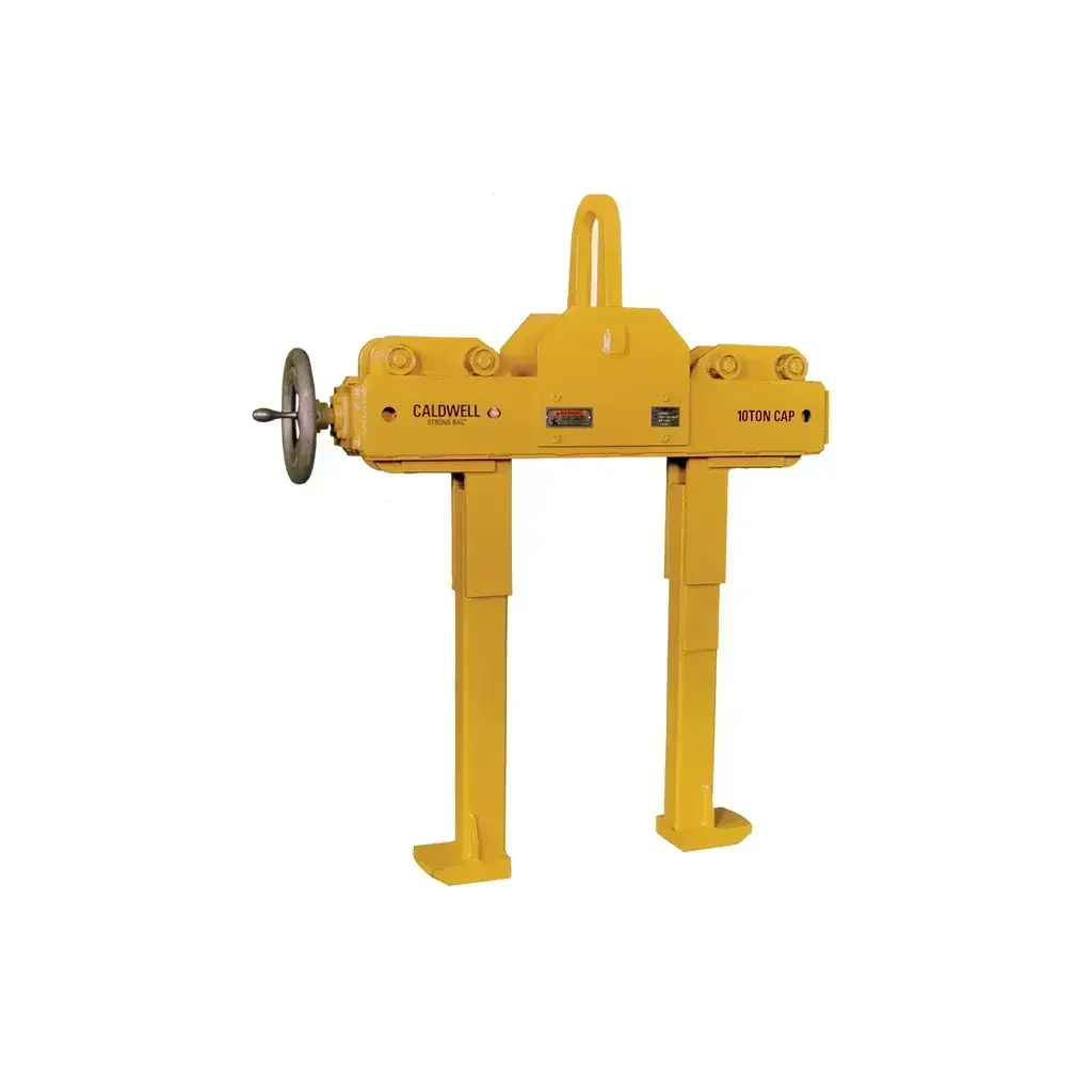
Caldwell Model F Beam Grab Construction Lifter
Caldwell Model F Beam Grab — Heavy-Duty Vertical Lifting for Wide Flange Beams & Plate Girders
The Caldwell Model F Beam Grab is a heavy-duty construction lifting clamp engineered for vertical handling of wide flange beam sections and plate girders. Designed for steel erection, structural fabrication, and heavy construction jobsites, this grab attaches directly to the beam flange without the need for slings or chokers — reducing rigging setup time and improving load control. The clamp features a recessed base to accept studs welded to a beam's surface, and operates on a self-tightening mechanical principle: the heavier the beam, the greater the clamping pressure applied by the center plate and gripping tongs. It complies with ASME standards, making it suitable for regulated jobsite environments.
Unlike conventional sling or choker rigging methods, the Model F eliminates the risk of sling slippage and dramatically reduces the time required to rig and de-rig each lift. Available in 5-, 15-, 25-, and 35-ton rated capacities, it accommodates a wide range of beam sizes and flange thicknesses, and can be used in pairs with a spreader/lifting beam for handling long girders. The 5-, 15-, and 25-ton models are stocked for immediate availability.
Key Features & Benefits
Self-Tightening Clamping Mechanism
When the grab is lifted, the center plate and gripping tongs work against each other to increase clamping pressure proportional to the load. This means the heavier the beam, the more secure the grip — providing a built-in safety margin that passive slings cannot replicate.
Eliminates Slings and Chokers
By clamping directly onto the beam flange, the Model F removes the need for wire rope slings or chain chokers entirely. This reduces rigging hardware costs, cuts setup and teardown time per lift, and eliminates a common source of load slippage on structural steel.
Recessed Base for Studded Beams
The clamp's base is machined with cutouts designed to clear studs welded to a beam's surface — a critical feature when handling composite beams with shear studs already installed. This prevents interference that would otherwise require re-positioning or damage the beam.
Heavy-Duty Design for Wide Flange Sections
Built for wide flange (W-shape) beams and plate girders, the Model F accommodates flange widths from 4 in. to 36 in. depending on model, and flange thicknesses from 0.25 in. up to 4 in. The robust steel construction supports rated capacities from 5 to 35 tons, covering the full range of typical structural steel lifting tasks.
Pair Usage with Spreader Beam for Long Loads
For long beams or girders where a single pick point would create excessive bending stress or instability, two Model F grabs can be used in tandem with a spreader or lifting beam. This provides balanced, stable lifts without specialized rigging hardware beyond the grabs themselves.
ASME-Compliant Construction
The Model F meets ASME standards for lifting devices, satisfying the requirements of regulated construction sites and inspections. Compliance documentation supports jobsite safety programs and reduces liability exposure for contractors and riggers.
Common Applications
Structural Steel Erection
The Model F is purpose-built for lifting and positioning wide flange beams during building frame erection, where speed and reliability of each pick cycle directly affect schedule and labor cost.
Bridge Girder Handling
Plate girders used in bridge construction are heavy, long, and often have welded studs — conditions the Model F is specifically designed to handle, including pair use with spreader beams for extended girder lengths.
Steel Fabrication Shop Lifts
In fabrication yards and shops, the Model F allows fast repositioning of beam sections between cutting, welding, and assembly stations without re-rigging slings between operations.
Composite Beam Handling
When handling beams with shear studs pre-welded to the top flange, the recessed base of the Model F clears the studs without interference — a common requirement on composite deck framing projects.
Industrial Material Handling
Beyond construction sites, the Model F is suited for any industrial environment where wide flange sections or heavy plate girders need to be moved vertically, including steel service centers and precast erection operations.
Heavy Lift Rigging with Spreader Beam
For crane picks on long, heavy girders, two Model F units paired with a spreader or lifting beam provide a controlled, balanced lift that single-point rigging cannot safely achieve.
Compatible Materials
- Wide flange (W-shape) structural steel beams
- Plate girders (steel)
- Composite beams with welded shear studs on flange surface
- Standard rolled steel beam sections within rated flange width and thickness ranges
- Heavy structural steel members up to 35-ton rated capacity
Available Models
| Model | Rated Capacity (tons) | Flange Width Range (in.) | Flange Thickness Range (in.) | Max Overall Width (in.) | Headroom (in.) | Weight (lbs.) | Best For |
|---|---|---|---|---|---|---|---|
| F-5 | 5 | 4 – 10 | 0.25 – 1.0 | 15.70 | 22.70 | 68 | Light structural beams; general framing picks; in-stock |
| F-15 | 15 | 8.5 – 17 | 0.25 – 2.0 | 25.10 | 30.10 | 210 | Medium structural steel; composite beams; bridge framing; in-stock |
| F-25 | 25 | 16 – 24 | 1.0 – 3.0 | 45.20 | 44.80 | 665 | Heavy wide flange sections; plate girders; in-stock |
| F-35 | 35 | 16 – 36 | 1.25 – 4.0 | 61.60 | 52.90 | 993 | Very heavy girders and plate sections; large-scale bridge and industrial lifts |
Product Documents
- Download Catalog — Model F Beam Grab Spec Sheet
- Download Evaluation Application Form — Extended Capacity Custom Units
Application Instructions
Pre-Lift Setup
- Verify the beam's weight is within the rated capacity of the selected Model F unit.
- Confirm the beam's flange width and flange thickness fall within the specified min/max range for the model being used.
- Inspect the grab for any visible damage, wear, or deformation before each use.
- If the beam has welded studs on the flange surface, confirm the recessed base cutouts will clear the studs without interference.
Attachment
- Lower the grab onto the beam, positioning the clamp body centered on the flange.
- If necessary, manually lift the tong arms to allow them to slide under the flanges of the beam.
- Ensure both tong arms are fully seated under both flanges before initiating the lift.
Lifting
- Use only for vertical lifting — do not use for angular or horizontal pulls.
- When the clamp is lifted, the center plate and gripping tongs engage automatically — do not attempt to manually tighten.
- For beams or girders longer than a single pick point can safely stabilize, use two Model F units in tandem with a spreader/lifting beam.
Release
- Lower the beam fully to its resting surface before releasing the grab.
- Once load tension is relieved, the tong arms can be manually lifted to disengage from the flange.
- Remove the grab and inspect for wear after heavy use cycles.
Technical Specifications
| Specification | F-5 | F-15 | F-25 | F-35 |
|---|---|---|---|---|
| Rated Capacity (tons) | 5 | 15 | 25 | 35 |
| Headroom — Dim. A (in.) | 22.70 | 30.10 | 44.80 | 52.90 |
| Max Overall Width — Dim. B (in.) | 15.70 | 25.10 | 45.20 | 61.60 |
| Inner Width — Dim. C (in.) | 11.60 | 17.50 | 24.50 | 28.50 |
| Min Flange Width (in.) | 4 | 8.5 | 16 | 16 |
| Max Flange Width (in.) | 10 | 17 | 24 | 36 |
| Min Flange Thickness (in.) | 0.25 | 0.25 | 1.25 | 1.25 (varies by width) |
| Max Flange Thickness (in.) | 1.0 | 2.0 | 3.0 | 4.0 |
| Cut Out Length (in.) | 2.0 | 2.5 | 5.5 | 6.0 |
| Cut Out Width (in.) | 3.0 | 4.0 | 6.0 (approx.) | 9.0 (approx.) |
| Distance Between Cut Outs (in.) | 4.6 | 7.3 | 9.8 | 4.5 (approx.) |
| Inner Length (in.) | 3.0 | 4.0 | — | — |
| Wall Thickness 1 (in.) | 0.50 | 0.90 | 1.30 | 0.80 |
| Wall Thickness 2 (in.) | 0.50 | 0.80 | 0.80 | 0.80 |
| Weight (lbs.) | 68 | 210 | 665 | 993 |
| Compliance Standard | ASME | |||
| Lift Direction | Vertical only | |||
| In-Stock Availability | Yes | Yes | Yes | Special order / eval required |
Safety Data Summary
Hazard Information
- This product is rated for vertical lifting only — angular, horizontal, or side pulls are strictly prohibited and will cause loss of grip and load drop.
- Overloading beyond rated capacity can result in clamp failure and dropped load.
- Do not use on beams with flange widths or thicknesses outside the specified min/max range for the model.
- Inspect the grab before each use — do not use damaged, deformed, or worn equipment.
Safe Handling
- Use only for vertical lifting — warning label is affixed to the product and must not be removed.
- For long beams or girders, always use two grabs in conjunction with a spreader/lifting beam to prevent uncontrolled load swing.
- Lower the load fully before attempting to remove the grab from the beam flange.
- Keep personnel clear of the suspended load at all times during lifting operations.
- Store in a dry location; inspect periodically for corrosion, wear on tong surfaces, and mechanical integrity of pivot points.
Frequently Asked Questions
Q: Can the Model F be used for angled or horizontal lifts?
A: No. The Model F is rated for vertical lifting only. Angular or horizontal loading compromises the self-tightening clamping mechanism and can result in load release. This restriction is enforced by ASME standards and is printed as a warning on the product.
Q: How does the clamping mechanism work — does it need to be manually tightened?
A: No manual tightening is required. When the grab is lifted, the center plate and gripping tongs act against each other mechanically. Clamping pressure increases proportionally with the weight of the suspended load, providing automatic and self-reinforcing grip throughout the lift.
Q: Can the Model F be used on beams with shear studs already welded to the flange?
A: Yes. The clamp base is machined with recessed cutouts specifically to clear studs welded to the beam surface. Verify that your specific stud size and pattern fall within the cutout dimensions for your model before use.
Q: Which models are available from stock, and which require lead time?
A: The F-5, F-15, and F-25 (5-, 15-, and 25-ton) models are stocked for immediate availability. The F-35 and any extended-capacity custom units (50-ton and above for special flange widths) require an application evaluation form and are built to order.
Q: How do I handle a long beam or plate girder safely with the Model F?
A: Use two Model F grabs in tandem, one at each end of the beam, connected via a spreader or lifting beam above. This distributes the load evenly, prevents bending stress at a single pick point, and maintains load stability during the lift.
Q: Is the Model F suitable for composite beams used in structural floor systems?
A: Yes, provided the flange width and thickness are within the model's rated range and the welded shear studs clear the recessed base cutouts. Review the cutout dimensions for the specific model against your stud layout before committing to a lift.
Product Information
Product Information
Shipping & Returns
Shipping & Returns


Caldwell Model F Beam Grab Construction Lifter
Caldwell Model F Beam Grab Construction Lifter
Caldwell Model F Beam Grab — Heavy-Duty Vertical Lifting for Wide Flange Beams & Plate Girders
The Caldwell Model F Beam Grab is a heavy-duty construction lifting clamp engineered for vertical handling of wide flange beam sections and plate girders. Designed for steel erection, structural fabrication, and heavy construction jobsites, this grab attaches directly to the beam flange without the need for slings or chokers — reducing rigging setup time and improving load control. The clamp features a recessed base to accept studs welded to a beam's surface, and operates on a self-tightening mechanical principle: the heavier the beam, the greater the clamping pressure applied by the center plate and gripping tongs. It complies with ASME standards, making it suitable for regulated jobsite environments.
Unlike conventional sling or choker rigging methods, the Model F eliminates the risk of sling slippage and dramatically reduces the time required to rig and de-rig each lift. Available in 5-, 15-, 25-, and 35-ton rated capacities, it accommodates a wide range of beam sizes and flange thicknesses, and can be used in pairs with a spreader/lifting beam for handling long girders. The 5-, 15-, and 25-ton models are stocked for immediate availability.
Key Features & Benefits
Self-Tightening Clamping Mechanism
When the grab is lifted, the center plate and gripping tongs work against each other to increase clamping pressure proportional to the load. This means the heavier the beam, the more secure the grip — providing a built-in safety margin that passive slings cannot replicate.
Eliminates Slings and Chokers
By clamping directly onto the beam flange, the Model F removes the need for wire rope slings or chain chokers entirely. This reduces rigging hardware costs, cuts setup and teardown time per lift, and eliminates a common source of load slippage on structural steel.
Recessed Base for Studded Beams
The clamp's base is machined with cutouts designed to clear studs welded to a beam's surface — a critical feature when handling composite beams with shear studs already installed. This prevents interference that would otherwise require re-positioning or damage the beam.
Heavy-Duty Design for Wide Flange Sections
Built for wide flange (W-shape) beams and plate girders, the Model F accommodates flange widths from 4 in. to 36 in. depending on model, and flange thicknesses from 0.25 in. up to 4 in. The robust steel construction supports rated capacities from 5 to 35 tons, covering the full range of typical structural steel lifting tasks.
Pair Usage with Spreader Beam for Long Loads
For long beams or girders where a single pick point would create excessive bending stress or instability, two Model F grabs can be used in tandem with a spreader or lifting beam. This provides balanced, stable lifts without specialized rigging hardware beyond the grabs themselves.
ASME-Compliant Construction
The Model F meets ASME standards for lifting devices, satisfying the requirements of regulated construction sites and inspections. Compliance documentation supports jobsite safety programs and reduces liability exposure for contractors and riggers.
Common Applications
Structural Steel Erection
The Model F is purpose-built for lifting and positioning wide flange beams during building frame erection, where speed and reliability of each pick cycle directly affect schedule and labor cost.
Bridge Girder Handling
Plate girders used in bridge construction are heavy, long, and often have welded studs — conditions the Model F is specifically designed to handle, including pair use with spreader beams for extended girder lengths.
Steel Fabrication Shop Lifts
In fabrication yards and shops, the Model F allows fast repositioning of beam sections between cutting, welding, and assembly stations without re-rigging slings between operations.
Composite Beam Handling
When handling beams with shear studs pre-welded to the top flange, the recessed base of the Model F clears the studs without interference — a common requirement on composite deck framing projects.
Industrial Material Handling
Beyond construction sites, the Model F is suited for any industrial environment where wide flange sections or heavy plate girders need to be moved vertically, including steel service centers and precast erection operations.
Heavy Lift Rigging with Spreader Beam
For crane picks on long, heavy girders, two Model F units paired with a spreader or lifting beam provide a controlled, balanced lift that single-point rigging cannot safely achieve.
Compatible Materials
- Wide flange (W-shape) structural steel beams
- Plate girders (steel)
- Composite beams with welded shear studs on flange surface
- Standard rolled steel beam sections within rated flange width and thickness ranges
- Heavy structural steel members up to 35-ton rated capacity
Available Models
| Model | Rated Capacity (tons) | Flange Width Range (in.) | Flange Thickness Range (in.) | Max Overall Width (in.) | Headroom (in.) | Weight (lbs.) | Best For |
|---|---|---|---|---|---|---|---|
| F-5 | 5 | 4 – 10 | 0.25 – 1.0 | 15.70 | 22.70 | 68 | Light structural beams; general framing picks; in-stock |
| F-15 | 15 | 8.5 – 17 | 0.25 – 2.0 | 25.10 | 30.10 | 210 | Medium structural steel; composite beams; bridge framing; in-stock |
| F-25 | 25 | 16 – 24 | 1.0 – 3.0 | 45.20 | 44.80 | 665 | Heavy wide flange sections; plate girders; in-stock |
| F-35 | 35 | 16 – 36 | 1.25 – 4.0 | 61.60 | 52.90 | 993 | Very heavy girders and plate sections; large-scale bridge and industrial lifts |
Product Documents
- Download Catalog — Model F Beam Grab Spec Sheet
- Download Evaluation Application Form — Extended Capacity Custom Units
Application Instructions
Pre-Lift Setup
- Verify the beam's weight is within the rated capacity of the selected Model F unit.
- Confirm the beam's flange width and flange thickness fall within the specified min/max range for the model being used.
- Inspect the grab for any visible damage, wear, or deformation before each use.
- If the beam has welded studs on the flange surface, confirm the recessed base cutouts will clear the studs without interference.
Attachment
- Lower the grab onto the beam, positioning the clamp body centered on the flange.
- If necessary, manually lift the tong arms to allow them to slide under the flanges of the beam.
- Ensure both tong arms are fully seated under both flanges before initiating the lift.
Lifting
- Use only for vertical lifting — do not use for angular or horizontal pulls.
- When the clamp is lifted, the center plate and gripping tongs engage automatically — do not attempt to manually tighten.
- For beams or girders longer than a single pick point can safely stabilize, use two Model F units in tandem with a spreader/lifting beam.
Release
- Lower the beam fully to its resting surface before releasing the grab.
- Once load tension is relieved, the tong arms can be manually lifted to disengage from the flange.
- Remove the grab and inspect for wear after heavy use cycles.
Technical Specifications
| Specification | F-5 | F-15 | F-25 | F-35 |
|---|---|---|---|---|
| Rated Capacity (tons) | 5 | 15 | 25 | 35 |
| Headroom — Dim. A (in.) | 22.70 | 30.10 | 44.80 | 52.90 |
| Max Overall Width — Dim. B (in.) | 15.70 | 25.10 | 45.20 | 61.60 |
| Inner Width — Dim. C (in.) | 11.60 | 17.50 | 24.50 | 28.50 |
| Min Flange Width (in.) | 4 | 8.5 | 16 | 16 |
| Max Flange Width (in.) | 10 | 17 | 24 | 36 |
| Min Flange Thickness (in.) | 0.25 | 0.25 | 1.25 | 1.25 (varies by width) |
| Max Flange Thickness (in.) | 1.0 | 2.0 | 3.0 | 4.0 |
| Cut Out Length (in.) | 2.0 | 2.5 | 5.5 | 6.0 |
| Cut Out Width (in.) | 3.0 | 4.0 | 6.0 (approx.) | 9.0 (approx.) |
| Distance Between Cut Outs (in.) | 4.6 | 7.3 | 9.8 | 4.5 (approx.) |
| Inner Length (in.) | 3.0 | 4.0 | — | — |
| Wall Thickness 1 (in.) | 0.50 | 0.90 | 1.30 | 0.80 |
| Wall Thickness 2 (in.) | 0.50 | 0.80 | 0.80 | 0.80 |
| Weight (lbs.) | 68 | 210 | 665 | 993 |
| Compliance Standard | ASME | |||
| Lift Direction | Vertical only | |||
| In-Stock Availability | Yes | Yes | Yes | Special order / eval required |
Safety Data Summary
Hazard Information
- This product is rated for vertical lifting only — angular, horizontal, or side pulls are strictly prohibited and will cause loss of grip and load drop.
- Overloading beyond rated capacity can result in clamp failure and dropped load.
- Do not use on beams with flange widths or thicknesses outside the specified min/max range for the model.
- Inspect the grab before each use — do not use damaged, deformed, or worn equipment.
Safe Handling
- Use only for vertical lifting — warning label is affixed to the product and must not be removed.
- For long beams or girders, always use two grabs in conjunction with a spreader/lifting beam to prevent uncontrolled load swing.
- Lower the load fully before attempting to remove the grab from the beam flange.
- Keep personnel clear of the suspended load at all times during lifting operations.
- Store in a dry location; inspect periodically for corrosion, wear on tong surfaces, and mechanical integrity of pivot points.
Frequently Asked Questions
Q: Can the Model F be used for angled or horizontal lifts?
A: No. The Model F is rated for vertical lifting only. Angular or horizontal loading compromises the self-tightening clamping mechanism and can result in load release. This restriction is enforced by ASME standards and is printed as a warning on the product.
Q: How does the clamping mechanism work — does it need to be manually tightened?
A: No manual tightening is required. When the grab is lifted, the center plate and gripping tongs act against each other mechanically. Clamping pressure increases proportionally with the weight of the suspended load, providing automatic and self-reinforcing grip throughout the lift.
Q: Can the Model F be used on beams with shear studs already welded to the flange?
A: Yes. The clamp base is machined with recessed cutouts specifically to clear studs welded to the beam surface. Verify that your specific stud size and pattern fall within the cutout dimensions for your model before use.
Q: Which models are available from stock, and which require lead time?
A: The F-5, F-15, and F-25 (5-, 15-, and 25-ton) models are stocked for immediate availability. The F-35 and any extended-capacity custom units (50-ton and above for special flange widths) require an application evaluation form and are built to order.
Q: How do I handle a long beam or plate girder safely with the Model F?
A: Use two Model F grabs in tandem, one at each end of the beam, connected via a spreader or lifting beam above. This distributes the load evenly, prevents bending stress at a single pick point, and maintains load stability during the lift.
Q: Is the Model F suitable for composite beams used in structural floor systems?
A: Yes, provided the flange width and thickness are within the model's rated range and the welded shear studs clear the recessed base cutouts. Review the cutout dimensions for the specific model against your stud layout before committing to a lift.
Original: $2,509.00
-65%$2,509.00
$878.15Product Information
Product Information
Shipping & Returns
Shipping & Returns
Description
Caldwell Model F Beam Grab — Heavy-Duty Vertical Lifting for Wide Flange Beams & Plate Girders
The Caldwell Model F Beam Grab is a heavy-duty construction lifting clamp engineered for vertical handling of wide flange beam sections and plate girders. Designed for steel erection, structural fabrication, and heavy construction jobsites, this grab attaches directly to the beam flange without the need for slings or chokers — reducing rigging setup time and improving load control. The clamp features a recessed base to accept studs welded to a beam's surface, and operates on a self-tightening mechanical principle: the heavier the beam, the greater the clamping pressure applied by the center plate and gripping tongs. It complies with ASME standards, making it suitable for regulated jobsite environments.
Unlike conventional sling or choker rigging methods, the Model F eliminates the risk of sling slippage and dramatically reduces the time required to rig and de-rig each lift. Available in 5-, 15-, 25-, and 35-ton rated capacities, it accommodates a wide range of beam sizes and flange thicknesses, and can be used in pairs with a spreader/lifting beam for handling long girders. The 5-, 15-, and 25-ton models are stocked for immediate availability.
Key Features & Benefits
Self-Tightening Clamping Mechanism
When the grab is lifted, the center plate and gripping tongs work against each other to increase clamping pressure proportional to the load. This means the heavier the beam, the more secure the grip — providing a built-in safety margin that passive slings cannot replicate.
Eliminates Slings and Chokers
By clamping directly onto the beam flange, the Model F removes the need for wire rope slings or chain chokers entirely. This reduces rigging hardware costs, cuts setup and teardown time per lift, and eliminates a common source of load slippage on structural steel.
Recessed Base for Studded Beams
The clamp's base is machined with cutouts designed to clear studs welded to a beam's surface — a critical feature when handling composite beams with shear studs already installed. This prevents interference that would otherwise require re-positioning or damage the beam.
Heavy-Duty Design for Wide Flange Sections
Built for wide flange (W-shape) beams and plate girders, the Model F accommodates flange widths from 4 in. to 36 in. depending on model, and flange thicknesses from 0.25 in. up to 4 in. The robust steel construction supports rated capacities from 5 to 35 tons, covering the full range of typical structural steel lifting tasks.
Pair Usage with Spreader Beam for Long Loads
For long beams or girders where a single pick point would create excessive bending stress or instability, two Model F grabs can be used in tandem with a spreader or lifting beam. This provides balanced, stable lifts without specialized rigging hardware beyond the grabs themselves.
ASME-Compliant Construction
The Model F meets ASME standards for lifting devices, satisfying the requirements of regulated construction sites and inspections. Compliance documentation supports jobsite safety programs and reduces liability exposure for contractors and riggers.
Common Applications
Structural Steel Erection
The Model F is purpose-built for lifting and positioning wide flange beams during building frame erection, where speed and reliability of each pick cycle directly affect schedule and labor cost.
Bridge Girder Handling
Plate girders used in bridge construction are heavy, long, and often have welded studs — conditions the Model F is specifically designed to handle, including pair use with spreader beams for extended girder lengths.
Steel Fabrication Shop Lifts
In fabrication yards and shops, the Model F allows fast repositioning of beam sections between cutting, welding, and assembly stations without re-rigging slings between operations.
Composite Beam Handling
When handling beams with shear studs pre-welded to the top flange, the recessed base of the Model F clears the studs without interference — a common requirement on composite deck framing projects.
Industrial Material Handling
Beyond construction sites, the Model F is suited for any industrial environment where wide flange sections or heavy plate girders need to be moved vertically, including steel service centers and precast erection operations.
Heavy Lift Rigging with Spreader Beam
For crane picks on long, heavy girders, two Model F units paired with a spreader or lifting beam provide a controlled, balanced lift that single-point rigging cannot safely achieve.
Compatible Materials
- Wide flange (W-shape) structural steel beams
- Plate girders (steel)
- Composite beams with welded shear studs on flange surface
- Standard rolled steel beam sections within rated flange width and thickness ranges
- Heavy structural steel members up to 35-ton rated capacity
Available Models
| Model | Rated Capacity (tons) | Flange Width Range (in.) | Flange Thickness Range (in.) | Max Overall Width (in.) | Headroom (in.) | Weight (lbs.) | Best For |
|---|---|---|---|---|---|---|---|
| F-5 | 5 | 4 – 10 | 0.25 – 1.0 | 15.70 | 22.70 | 68 | Light structural beams; general framing picks; in-stock |
| F-15 | 15 | 8.5 – 17 | 0.25 – 2.0 | 25.10 | 30.10 | 210 | Medium structural steel; composite beams; bridge framing; in-stock |
| F-25 | 25 | 16 – 24 | 1.0 – 3.0 | 45.20 | 44.80 | 665 | Heavy wide flange sections; plate girders; in-stock |
| F-35 | 35 | 16 – 36 | 1.25 – 4.0 | 61.60 | 52.90 | 993 | Very heavy girders and plate sections; large-scale bridge and industrial lifts |
Product Documents
- Download Catalog — Model F Beam Grab Spec Sheet
- Download Evaluation Application Form — Extended Capacity Custom Units
Application Instructions
Pre-Lift Setup
- Verify the beam's weight is within the rated capacity of the selected Model F unit.
- Confirm the beam's flange width and flange thickness fall within the specified min/max range for the model being used.
- Inspect the grab for any visible damage, wear, or deformation before each use.
- If the beam has welded studs on the flange surface, confirm the recessed base cutouts will clear the studs without interference.
Attachment
- Lower the grab onto the beam, positioning the clamp body centered on the flange.
- If necessary, manually lift the tong arms to allow them to slide under the flanges of the beam.
- Ensure both tong arms are fully seated under both flanges before initiating the lift.
Lifting
- Use only for vertical lifting — do not use for angular or horizontal pulls.
- When the clamp is lifted, the center plate and gripping tongs engage automatically — do not attempt to manually tighten.
- For beams or girders longer than a single pick point can safely stabilize, use two Model F units in tandem with a spreader/lifting beam.
Release
- Lower the beam fully to its resting surface before releasing the grab.
- Once load tension is relieved, the tong arms can be manually lifted to disengage from the flange.
- Remove the grab and inspect for wear after heavy use cycles.
Technical Specifications
| Specification | F-5 | F-15 | F-25 | F-35 |
|---|---|---|---|---|
| Rated Capacity (tons) | 5 | 15 | 25 | 35 |
| Headroom — Dim. A (in.) | 22.70 | 30.10 | 44.80 | 52.90 |
| Max Overall Width — Dim. B (in.) | 15.70 | 25.10 | 45.20 | 61.60 |
| Inner Width — Dim. C (in.) | 11.60 | 17.50 | 24.50 | 28.50 |
| Min Flange Width (in.) | 4 | 8.5 | 16 | 16 |
| Max Flange Width (in.) | 10 | 17 | 24 | 36 |
| Min Flange Thickness (in.) | 0.25 | 0.25 | 1.25 | 1.25 (varies by width) |
| Max Flange Thickness (in.) | 1.0 | 2.0 | 3.0 | 4.0 |
| Cut Out Length (in.) | 2.0 | 2.5 | 5.5 | 6.0 |
| Cut Out Width (in.) | 3.0 | 4.0 | 6.0 (approx.) | 9.0 (approx.) |
| Distance Between Cut Outs (in.) | 4.6 | 7.3 | 9.8 | 4.5 (approx.) |
| Inner Length (in.) | 3.0 | 4.0 | — | — |
| Wall Thickness 1 (in.) | 0.50 | 0.90 | 1.30 | 0.80 |
| Wall Thickness 2 (in.) | 0.50 | 0.80 | 0.80 | 0.80 |
| Weight (lbs.) | 68 | 210 | 665 | 993 |
| Compliance Standard | ASME | |||
| Lift Direction | Vertical only | |||
| In-Stock Availability | Yes | Yes | Yes | Special order / eval required |
Safety Data Summary
Hazard Information
- This product is rated for vertical lifting only — angular, horizontal, or side pulls are strictly prohibited and will cause loss of grip and load drop.
- Overloading beyond rated capacity can result in clamp failure and dropped load.
- Do not use on beams with flange widths or thicknesses outside the specified min/max range for the model.
- Inspect the grab before each use — do not use damaged, deformed, or worn equipment.
Safe Handling
- Use only for vertical lifting — warning label is affixed to the product and must not be removed.
- For long beams or girders, always use two grabs in conjunction with a spreader/lifting beam to prevent uncontrolled load swing.
- Lower the load fully before attempting to remove the grab from the beam flange.
- Keep personnel clear of the suspended load at all times during lifting operations.
- Store in a dry location; inspect periodically for corrosion, wear on tong surfaces, and mechanical integrity of pivot points.
Frequently Asked Questions
Q: Can the Model F be used for angled or horizontal lifts?
A: No. The Model F is rated for vertical lifting only. Angular or horizontal loading compromises the self-tightening clamping mechanism and can result in load release. This restriction is enforced by ASME standards and is printed as a warning on the product.
Q: How does the clamping mechanism work — does it need to be manually tightened?
A: No manual tightening is required. When the grab is lifted, the center plate and gripping tongs act against each other mechanically. Clamping pressure increases proportionally with the weight of the suspended load, providing automatic and self-reinforcing grip throughout the lift.
Q: Can the Model F be used on beams with shear studs already welded to the flange?
A: Yes. The clamp base is machined with recessed cutouts specifically to clear studs welded to the beam surface. Verify that your specific stud size and pattern fall within the cutout dimensions for your model before use.
Q: Which models are available from stock, and which require lead time?
A: The F-5, F-15, and F-25 (5-, 15-, and 25-ton) models are stocked for immediate availability. The F-35 and any extended-capacity custom units (50-ton and above for special flange widths) require an application evaluation form and are built to order.
Q: How do I handle a long beam or plate girder safely with the Model F?
A: Use two Model F grabs in tandem, one at each end of the beam, connected via a spreader or lifting beam above. This distributes the load evenly, prevents bending stress at a single pick point, and maintains load stability during the lift.
Q: Is the Model F suitable for composite beams used in structural floor systems?
A: Yes, provided the flange width and thickness are within the model's rated range and the welded shear studs clear the recessed base cutouts. Review the cutout dimensions for the specific model against your stud layout before committing to a lift.